Category Archives: scratch

Zusatzaufgabe scratch, Rechtecke

Stift-Malerei mit dem Malstift
Male Bilder auf die Bühne

rechteck_1_1

rechteck_2_2

rechteck_3_geschachtelt

rechteck_4_zeilenspalten

rechteck_5_geschachtelt2

palette_malstift 
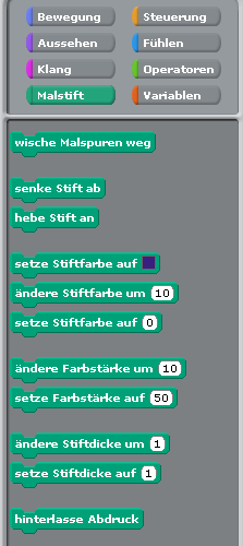
Wenn man Figuren bewegt, dann können diese bei der Bewegung Linien auf die Bühne malen. Dazu sind die ‚Malstift‘-Blöcke vorhanden.

Die folgenden Aufgaben sind als Erweiterung zum scratch-Kurs vorgesehen und sollen das Gelernte vertiefen.

Speichert die verschiedenen Programme auf der SD-Karte.


Aufgabe 1, Ein einfaches  Quadrat.

rechteck_1_1

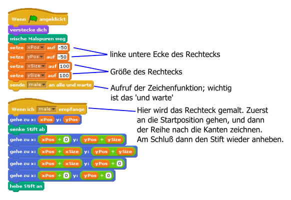
Male mit dem Stift ein Quadrat auf die Bühne, Seitenlänge 100, Position -50,-50 (die linke untere Ecke).

Es gibt mehrere Möglichkeiten für die Lösung.

Programmstruktur

Da solche Quadrate jetzt in vielen verschiedenen Kombinationen verwendet werden lohnt es sich etwas Arbeit in die Programmstruktur zu stecken.

Wenn man Quadrate oder Rechtecke in verschiedenen Größen und Positionen malen will, dann sollte man die Größe und Position in Variablen speichern und dann mit der ‚Sende und Warte‘-Funktion ein anderes Skript aufrufen, was dann die eigentliche Zeichenaufgabe über­nimmt.

rechteck_programmstruktur

Das Programm in scratch abtippen und laufen lassen.

Der ‚Sende und Warte‘ -Block kann nicht nur für Quadrate angewendet werden, sondern immer dann wenn man wiederholende Aufgaben ausführen will.

 Aufgabe 2: Zwei (?) Quadrate

rechteck_2_2

Man kann das Programm einfach erweitern, um zwei Quadrate zu malen.
Zusatzaufgabe: wieviele Quadrate siehst Du auf der Bühne ??

rechteck_2_script

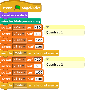
Das Programm wird einfach erweitert Zuerst wird das erste Quadrat gezeichnet, dann etwas verschoben das zweite Quadrat.

Aufgabe: erweitere das bisherige Programm und überprüfe, ob das gewünschte Ergebnis erhalten wird.

Aufgabe 3: Viele Rechtecke !!!!!

rechteck_3_geschachteltBisher waren nur sehr wenige Quadrate auf der Bühne. Wenn man sehr viele Quadrate haben möchte, dann wird das ‚Untereinanderschreiben‘ von Zeichenbefehlen sehr mühsam. Dafür sollten Programmschleifen verwendet werden.

Aufgabe: Zeichne die Rechtecke.

Das grösste Quadrat ist an Position -160, -160, die Größe ist 320.

Der Pseudocode sieht so aus:

verstecke dich
wische malspuren weg
setze xPos auf -160
setze yPos auf -160
setze xSize auf 320
setze ySize auf 320
wiederhole 32 mal
    send male an alle und warte
    ändere xSize um -10
    ändere ySize um -10
    ändere xPos um 5
    ändere yPos um 5

Bei jedem Schleifendurchlauf wird die Position des Quadrats etwas verschoben und die Größe etwas kleiner.

 Aufgabe 4: Zeilen und Reihen

  rechteck_4_zeilenspaltenEs ist klar, dass man „wiederhole“-Schleifen braucht.

Eine Wiederhole-Schleife für die Zeilen, und darin enthalten eine zweite Wiederhole-Schleife für die einzelnen Quadrate innerhalb der Zeile.

Aufgabe 5: Verschachtelt

 rechteck_5_geschachtelt2Dieses Beispiel kann aus den ineinander geschachtelten Rechtecken abgeleitet werden.

Beispiellösungen

Rechteck 1

Rechteck 2

Rechteck_3

Rechteck 4

Rechteck 5


pi and more 9, workshop ‘raspberry, scratch, gpio’

For the ‘pi and more 9‘ in Trier on 11 june 2016, I had the chance to run a workshop on how to use scratch with gpioserver and as an alternative to use scratch with scratchClient.
Basis setup was to control three LED with a button.

The introduction is available as a pdf-document.
The tutorials are available here: tutorial (de), tutorial (en).

Working with gpioserver was found to be unstable. Quite a few  attendants had problems to get a connection to the hardware. It simply did not work, or they got popups in scratch that connection to pigpiod could not be established. It was needed to stop scratch and restart to get it running. A reboot of the computer was needed to cure the problems where scratch complained about missing pigpio.
In the scratch startup shell script, there is a check for pigpiod, and when not running this code is started. Obviously this does not work stable.

The differences between using gpioserver and scratchClient have been clearly visible in this workshop:
gpioserver does not complain about misspelled commands, and there is no monitoring capability for this tool. So when something is wrong, it is difficult to find the problem.
scratchClient needs an additional tool to be started, and multiple startups have been a problem. But the monitoring features with the web tool  localhost:8080 have been acknowledged as valuable in training environments.


scratch io response times

Scratch 1.4 on raspberry pi allows programs to work with GPIO pins. I was curious to see how fast scratch can react to input values.

To measure these times, I connected an arduino due (84MHz clock) with a raspberry pi 2B. The arduino produces a 0–>1 edge for scratch and scratch responds with a 0–>1-edge on another pin. The red arrow in the chart shows this dependency. The time between these two edges is the response time of scratch. timing

The scratch code is straightforward. Sensor values are 0, 1, so there are logical operations needed.

.scratch_response_times

Response times are aggregated in a chart. X-axes shows the time intervals, y-axis shows how often execution times have been measured in the 0.5 ms intervals.

response_times

The response times range from  3ms to 46ms. The bulk of values is between 5ms and 27ms. The chart is produced from 5659 single measurements. So scratch is sufficient fast to respond in slow environments, but should not be used to control fast systems.

Here the arduino code:

//
// run on an arduino due

int pout = 11;
int pin = 12;

void setup() {
  Serial.begin(9600);
  while (!Serial) {
    ; // wait for serial port to connect. Needed for native USB port only
  }
  Serial.println("response_time_measurement");
  pinMode(pin, INPUT);
  pinMode(pout, OUTPUT);
  digitalWrite(pout, LOW);
}
long randomnumber = 0;
long t0 = 0;
long t1 = 0;

void loop() {
  // wait for input low
  while ( HIGH == digitalRead(pin)) ;

  randomnumber = random(1, 700);
  delay(randomnumber);
  t0 = micros();
  digitalWrite(pout, HIGH);

  while ( LOW == digitalRead(pin)) ;
  t1 = micros();

  Serial.print(randomnumber);
  Serial.print("\t");
  Serial.println(t1 - t0);

  delay(100);
  digitalWrite(pout, LOW);
}

There is a variable delay in the arduino code from 1 to 700ms to prevent a ‘lock in’ to scratch cycle times.

Although time measurements are in microseconds, the accuracy depends on how good the compiler is in producing fast code. As the times to be measured are in millisecond range, this approach is reasonable precise.

Similiar setup with scratchClient yields following results:

response_times_scratchClient

Times are centered around some 67 ms, min is 46 ms which is slower than using gpioserver.

The scratchClient-adapter used is ‘GpioButtonInput’, which already provides edge-detection. The scratch code is

scratch_scratchClient_performance


Zusatzaufgabe scratch, Palindrom-Checker

Ein Palindrom ist ein Wort, das vorwärts wie rückwärts einen Sinn ergibt. Idealerweise sogar denselben Sinn, wie  “Lagerregal”.

Satzpalindrome sind  “Ein Eis esse sie nie.”. Hier werden Leerzeichen und Satzzeichen ignoriert und Groß- und Kleinschreibung wird ebenfalls ignoriert.

Die erste Aufgabe ist: Überprüfe ein Wort ob es ein Palindrom ist

Das Wort mit der Antwort-Methode einlesen und dann überprüfen. Da scratch keine Methode zur Korrektur von Groß- und Kleinschreibung hat, sollen nur Kleinbuchstaben und Zahlen eingegeben werden.

Schon eine Idee wie man das machen kann ? Einen Hinweis gibt es hier.

Das Programm soll ‘das ist ein Palindrom’ sagen. Oder eben auch ‘sorry, kein Palindrom’.


Die zweite Aufgabe ist: Überprüfe auch Satzpalindrome.

palindrom

Das Programm aus Aufgabe 1 so erweitern, dass Leerzeichen und Satzzeichen wie !?.,: entfernt werden.


LEGO powerfunctions control with scratch 1.4

LEGO has a nice set of controls named ‘powerfunctions’. The main device is a IR-receiver which can control motors, LED with a variety of functions. ON,OFF, PWM are available.

To connect this to scratch I use an arduino to control the IR-LED. Arduino is connected by USB to raspberry pi.

The LED is connected to the arduino UNO on a breadboard. I had one from an earlier experiment already mounted to a small board. When arduino outputs are used, current for the LED is limited to 20mA. With an external transistor, current and thus the range can be increased. With my setup range was prox one to two meter.

arduinoUNO_Powerfunctions_Steckplatine_r2016-03-27

The setup shown uses an arduino UNO. It is also possible to use an arduino NANO instead. Other arduino boards like mega,zero due should be possible, but not tested.

Arduino code uses a library from a library https://github.com/jurriaan/Arduino-PowerFunctions with small modifications.

The code can control up to four channels. The LEGO RC protocol used is ‘Combo PWM mode’. The timeout needed is handled by the scratch Adapter, resending commands each 0.3 sec.

With a mobile camera, it is possible to make the IR LED light visible. The sensors used in camera have a broad sensitivity area and record IR light too.

ir_led

In scratch are a few variables needed like c_4_A or c_4_B for the channel 4 ‘red’ or ‘blue’ signals. Values are -7 to +7 for backward max speed to forward max speed;, as a special value ‘BREAK’ can be used.

Adjust USB connection in config file config/config_arduino_powerfunctions.xml

Start scratchClient with

cd ~/scratchClient
python src/scratchClient.py -c config/config_arduino_powerfunctions.xml

powerfunctions_script

When variables are available, a sample script is quite easy. This script was used to record the video.

Revisions:
2016-03-27 updated fritzing chart: LED connection now GND to PIN12 with resistor.

raspberry pi scratch 1.4 sound recording

Scratch 1.4 can record sound. But unfortunately the setup is not simple.

The comments here are based on raspbian 2016-02-26 and scratch 2016-01-15.

Recording sound in scratch 1.4

I connected a simple USB sound card. This card is connected to a microphone and a pair of speakers. The reason to use a card like this is especially the mic-input. Raspberry pi does not have an input on board.

sound_device

Doublecheck that your adapter is recognized from operating system. Open a terminal window ad enter ‘lsusb’. The output should show your sound device, here the output from my system:

pi@raspberrypi:~ $ lsusb
Bus 001 Device 009: ID 0d8c:013c C-Media Electronics, Inc. CM108 Audio Controller

On desktop, the proper audio device needs to be selected.

device_selection

I had to reboot the computer to get the changes working. The ‘unable to connect…’-popup clearly indicates that there are errors.

device_not_found

In scratch, check the audio output first. Let the cat ‘meow’ a few times.

record_start

Start recording with ‘New sound, record’. The sound recorder popup should be displayed. The red button starts recording.

sound_volume

There is a nice volume indication shown in the bar.

Press stop ■ and ok. The recording is available now.

Unfortunately, the sound was played double the speed, faster and higher than recorded. Seems to be a bug in scratch. Exporting the audio file to file system and importing this back results in normal playback.

There is no possibility to control recording by program code.

Advanced commands for command line

On my system, it was possible to record sound from mic by

arecord -D plughw:1,0 test.wav

With aplay it is possible to reply these data

 aplay -D plughw:1,0 test.wav

Recording sound and playback sound with scratchClient

Recording sound is possible with scratchClient controlled by scratch runtime.
This functionality is implemented by calling linux commands ‘arecord’ and ‘aplay’.

The adapter needed is ‘adapter.linux.Linux_ARECORD_Adapter’. It stores the files in a predefined directory. It uses the linux arecord command. You need to be familiar with alsa devices; this device needs to be specified.

Sample script is

linux_arecord

Set the file name, then start recording and stop as needed. There is a timeout specified in the adapter config.

Sample config file is config/config_linux_arecord.xml

Playback can be done by adapter adapter.linux.Linux_APLAY_Adapter. Sample script is

linux_aplay

Replay one file in a loop needs to set the file name ‘wave’ to blank in between, as only changing names are transmitted to scratchClient.

Sample config file is config/config_linux_aplay.xml

The files recorded or available for playback are NOT included in the scratch code. So when you move your scratch application to another computer, you need to move your files too.

Use same directory for record and playback, when a scratch program needs play earlier recorded sound.


scratch broadcast event handling

scratch 1.4 is sometimes good for a surprise. In school, a program of a pupil reacted unexpected: Obviously the event driven script did not complete operation, but was stopped by a second event.

A detailed analysis lead to this test code, demonstrating the behavior of event triggered code.

One of the observations are that scratch event handling is not multithreaded, but a new event stops current processing and restarts script.

scratch_boadcast_even_handlingThe sample here uses a simple script, triggered by ‘tick’ event. On entry, a variable ‘a’ is incremented, on exit of the script the variable is decremented. When the script is executed from start to end, then the variable will have same value at the end as at the beginning.


Triggering this script with a ‘slow’ loop (use ‘s’ key), uses a loop with two sec delay. In this scenario, the variable keeps the value.

Using the ‘fast’ loop (use ‘f’-key), the script receives a new tick event when just in the middle of operation. Obviously the script gets interrupted and restarts from beginning. This is clearly visible, as the variable gets incremented.


The ‘c’ key resets the logic.


The full scratch code 1.4 code is here for download broadcast_event_handling.sb.


gpioServer and scratchClient performance comparison for stepper driving signals

GPIO performance on raspberry pi is an often discussed topic.

New scratch uses a build in gpioServer, other options are scratchClient.
Especially stepper motors need quite high pulse rate, so I have set up a test harness for a small stepper with 2ms step width. The scenario are

  • a DMA pulse driven approach
  • a python program
  • scratch, using scratchClient
  • scratch, using GPIOserver

The main focus is on performance of scratch to GPIO.
For scratchClient, some bottleneck analysis is performed.

DMA created pulses

As expected, DMA pulse widths are precise. The glitch on third line is due to a limitation in my modified RPIO.PWM-library which does not yet allow impulse roll over. The interval time printed on the image is for four steps and precise 8ms.

dma

dma-impulse

This DMA approach is listed for reference only, as it is not easily controllable from scratch. It is either on or off, but number of pulses can’t be determined.

python created pulses

python code is also pretty good. Pulse with is exceeding the expected 8ms by 0.5ms, which could quite easily compensated by some more advanced time handling.

pythonpython

scratch and scratchClient

The scratchClient approach is expected to be slower. Time scale is changed for this chart and the result is 326ms for 4 steps, which is 40 times slower than python or DMA.

scratch_variables_scratchClient

scratchclient

scratch with gpioserver

GPIOserver, build in into scratch, is finally at 101ms, three times faster than scratch with scratchClient, only 12 times slower than python. The assymmetric pulses are due to to ‘forever loop’, I suppose.

scratch_gpioservergpioserver

All of the measurements have been taken on a RPI2, Model B, raspbian ‘jessie’, scratch is 2015-11-11.
Python is 2.7, the DMA code is a modified RPIO.PWM, adjusted for PI2.

scratchClient bottleneck analysis

The result for scratchClient was unexpectedly bad. So I have set up some tests to find out where the bottleneck is located.

scratch_broadcast_scratchClient

First approach was to change the variable based communication to the stepper module by an event based ‘broadcast’. This approach resulted in 101ms cycle time, a good match to the result from GPIOserver.

Second approach was to write a small python code which simulates scratch: a socket server for port 42001, sending out sensor updates like “sensor-update “br0.0” 0 “.

python_variables_scratchClient

python_scratchclient

The delay time was 2ms, and the result from this is a cycle time of 9ms. Pretty close to the pure python approach.
From these results it is clear that the bottleneck is on scratch side. Looks as if scratch variable access and sending them out is three times slower than sending out broadcasts from scratch.
Socket communication imposes some overhead, but is not limiting performance.

See also scratch performance 2, gpioserver reaction time

blink(1) for scratch

blink(1) is a neat small USB device with two RGB LED inside. See also their home page.

blink

The scratch code is straightforward. With variable ‘led_1’ the LED#1 is set, and ‘led_2’ sets LED#2. The device supports also a setAll-Command, a variable ‘led_all’ or ‘led_0’ is used for this purpose.

Download and install scratchClient-Software. In addition to the usual installation of scratchClient it is needed to install ‘pyusb’. This installation is described in the documentation.

scratchClient is designed to work with raspberry pi, but as pyusb is available on linux in general, this should be generally available on these platforms.

Start scratchClient with

cd ~/scratchClient
python src/scratchClient.py -c config_blink

blink.sb

This is the sample scratch Code from the animation. The two led are controlled by a small delay.

Basically, there is the possibility to use more than one blink(1) device. These are identified by their serial number, which can be used to control them separately. Drop me a note if you need this feature.

The usb-control software needs some additional installation, see the the installation remarks in barcode scanner for details.

Zusatzaufgabe scratch, Labyrinth

Einen Weg aus einem Labyrinth zu finden ist keine einfache Aufgabe. Es gibt verschiedene Typen von Labyrinthen, das hier gezeichnete ist eine freundliche Variante, die keine Rundwege enthält.

Die Wege sind dunkel gezeichnet und der Ausgang ist am Rand.lab_2

Die Aufgabe ist, dass eine kleine Figur den Weg zum Ausgang findet.stage_seek

Einige Beispiele für Wege sind in dem Beispielprogramm Labyrinth enthalten, siehe Bühne.
Die Rastergrösse ist 30 Pixel in dem Beispiel.

Das Sprite ‘seeker’ aus dem Beispiel hat die richtige Grösse für die Wege. Diese Figur kann auf einem Weg positioniert werden und durch Klick auf die Figur wird diese auf dem Weg zentriert.

Ab diesem Punkt beginnt die Aufgabe: schreibe ein Programm, das den Weg aus dem Labyrinth findet. Egal wo die Figur positioniert wird.

Schritt1: Beispielprogramm Labyrinth laden.
Schritt2: Welche Möglichkeiten gibt es, den Weg aus einem Labyrinth zu finden ?
Schritt3: Programmiere den Lösungsablauf und überprüfe mit verschiedenen Startpunkten und Hintergründen, ob das Programm funktioniert.

Hinweise: im Internet gibt es einige Beschreibungen, wie man aus Labyrinthen entkommen kann.

Die Aufgabe ist schwierig. Wenn auch die Lösung dann mit etwa 30 Blöcken nicht sehr gross wird.

Das Beispiel wurde in Anlehnung an http://www.inf-schule.de/programmierung/scratch/algorithmen/uebungen entwickelt.