Category Archives: scratchClient

scratchClient related things

LEGO powerfunctions control with scratch 1.4

LEGO has a nice set of controls named ‘powerfunctions’. The main device is a IR-receiver which can control motors, LED with a variety of functions. ON,OFF, PWM are available.

To connect this to scratch I use an arduino to control the IR-LED. Arduino is connected by USB to raspberry pi.

The LED is connected to the arduino UNO on a breadboard. I had one from an earlier experiment already mounted to a small board. When arduino outputs are used, current for the LED is limited to 20mA. With an external transistor, current and thus the range can be increased. With my setup range was prox one to two meter.

arduinoUNO_Powerfunctions_Steckplatine_r2016-03-27

The setup shown uses an arduino UNO. It is also possible to use an arduino NANO instead. Other arduino boards like mega,zero due should be possible, but not tested.

Arduino code uses a library from a library https://github.com/jurriaan/Arduino-PowerFunctions with small modifications.

The code can control up to four channels. The LEGO RC protocol used is ‘Combo PWM mode’. The timeout needed is handled by the scratch Adapter, resending commands each 0.3 sec.

With a mobile camera, it is possible to make the IR LED light visible. The sensors used in camera have a broad sensitivity area and record IR light too.

ir_led

In scratch are a few variables needed like c_4_A or c_4_B for the channel 4 ‘red’ or ‘blue’ signals. Values are -7 to +7 for backward max speed to forward max speed;, as a special value ‘BREAK’ can be used.

Adjust USB connection in config file config/config_arduino_powerfunctions.xml

Start scratchClient with

cd ~/scratchClient
python src/scratchClient.py -c config/config_arduino_powerfunctions.xml

powerfunctions_script

When variables are available, a sample script is quite easy. This script was used to record the video.

Revisions:
2016-03-27 updated fritzing chart: LED connection now GND to PIN12 with resistor.

gpioServer and scratchClient performance comparison for stepper driving signals

GPIO performance on raspberry pi is an often discussed topic.

New scratch uses a build in gpioServer, other options are scratchClient.
Especially stepper motors need quite high pulse rate, so I have set up a test harness for a small stepper with 2ms step width. The scenario are

  • a DMA pulse driven approach
  • a python program
  • scratch, using scratchClient
  • scratch, using GPIOserver

The main focus is on performance of scratch to GPIO.
For scratchClient, some bottleneck analysis is performed.

DMA created pulses

As expected, DMA pulse widths are precise. The glitch on third line is due to a limitation in my modified RPIO.PWM-library which does not yet allow impulse roll over. The interval time printed on the image is for four steps and precise 8ms.

dma

dma-impulse

This DMA approach is listed for reference only, as it is not easily controllable from scratch. It is either on or off, but number of pulses can’t be determined.

python created pulses

python code is also pretty good. Pulse with is exceeding the expected 8ms by 0.5ms, which could quite easily compensated by some more advanced time handling.

pythonpython

scratch and scratchClient

The scratchClient approach is expected to be slower. Time scale is changed for this chart and the result is 326ms for 4 steps, which is 40 times slower than python or DMA.

scratch_variables_scratchClient

scratchclient

scratch with gpioserver

GPIOserver, build in into scratch, is finally at 101ms, three times faster than scratch with scratchClient, only 12 times slower than python. The assymmetric pulses are due to to ‘forever loop’, I suppose.

scratch_gpioservergpioserver

All of the measurements have been taken on a RPI2, Model B, raspbian ‘jessie’, scratch is 2015-11-11.
Python is 2.7, the DMA code is a modified RPIO.PWM, adjusted for PI2.

scratchClient bottleneck analysis

The result for scratchClient was unexpectedly bad. So I have set up some tests to find out where the bottleneck is located.

scratch_broadcast_scratchClient

First approach was to change the variable based communication to the stepper module by an event based ‘broadcast’. This approach resulted in 101ms cycle time, a good match to the result from GPIOserver.

Second approach was to write a small python code which simulates scratch: a socket server for port 42001, sending out sensor updates like “sensor-update “br0.0” 0 “.

python_variables_scratchClient

python_scratchclient

The delay time was 2ms, and the result from this is a cycle time of 9ms. Pretty close to the pure python approach.
From these results it is clear that the bottleneck is on scratch side. Looks as if scratch variable access and sending them out is three times slower than sending out broadcasts from scratch.
Socket communication imposes some overhead, but is not limiting performance.

See also scratch performance 2, gpioserver reaction time

blink(1) for scratch

blink(1) is a neat small USB device with two RGB LED inside. See also their home page.

blink

The scratch code is straightforward. With variable ‘led_1’ the LED#1 is set, and ‘led_2’ sets LED#2. The device supports also a setAll-Command, a variable ‘led_all’ or ‘led_0’ is used for this purpose.

Download and install scratchClient-Software. In addition to the usual installation of scratchClient it is needed to install ‘pyusb’. This installation is described in the documentation.

scratchClient is designed to work with raspberry pi, but as pyusb is available on linux in general, this should be generally available on these platforms.

Start scratchClient with

cd ~/scratchClient
python src/scratchClient.py -c config_blink

blink.sb

This is the sample scratch Code from the animation. The two led are controlled by a small delay.

Basically, there is the possibility to use more than one blink(1) device. These are identified by their serial number, which can be used to control them separately. Drop me a note if you need this feature.

The usb-control software needs some additional installation, see the the installation remarks in barcode scanner for details.

Sense Hat, Astro Pi connected to scratch

Sense Hat (announcement by raspbery pi foundation) is an add on board for PI2, which supports environmental sensors for temperature, pressure and humidity. There is an IMU-sensor included. And a fancy 8×8 RGB-LED matrix. And a small joystick which provides cursor keys and the enter key for the center button.

The software to drive this board is wrapped in a python API. This APi is handy to be used for scratchClient and connect it to scratch.

The adapter is adapter.senseHat_adapter.SenseHat_Adapter.

LED Matrix

Events are ‘clear’, setPixel_xy’ and ‘clearPixel_xy’.

‘clear’ is pretty straightforward and clears the matrix to blank.

The pixel operations need variables to be set before the setPixel can be performed.

procedureCall
x and y position needs to be set and the color needed. The event sense_led_xy_on is mapped to setPixel_xy by scratchClient. This mapping is done in the configuration for this adapter (scratchClient/scratch/senseHat/config_senseHat.xml).

        <input name= 'clear'>
            <broadcast name='sense_led_clear'/>
        </input>
        
        <input name= 'setPixel_xy'>
            <broadcast name='sense_led_xy_on'/>
        </input>
        
        <input name= 'clearPixel_xy'>
            <broadcast name='sense_led_xy_off'/>
        </input>

The commands available in scratch are the <broadcast/> elements. These all have the prefix ‘sense_’.

Color supports basic colors in plain english (red, green, white, blue, and some more) and ‘#aabbcc’ which is hex notation in red, green blue. In the  scratchClient documentation are the details, look for the ‘colorType’-definition in chapter ‘Adapter Data Types’ .

In my experiments, I found that small rgb-values for the LED, e.g. #030303, which is red=3, green=3, blue=3 are not displayed, but leave the LED dark. Obviously the API is doing some gamma correction and discards small values. Try higher values if you run into this problem. #303030 seem to be smallest values available.

For the clearPixel call, no color needs to be set.

There is a scratch sample application scratchClient/scratch/senseHat/sense_hat_led.sb which allows to set/clear pixel in a (hopefully) intuitive way. Move the blue cursor mark with cursor keys and toggle the LED by blank key.

led_control

Stage printout

The joystick on senseHat can be used to move the cursor around. Unfortunately the center button sends ‘enter’, which is the ‘green flag event’ in scratch and restarts the code. Thus the toggle LED is mapped to the blank bar on keyboard for this sample.

led-matrix

A LED pattern, camera shutter time 1/60 sec

led-matrix-2

Same LED pattern, camera shutter time 1/100 sec displaying only part of the LED

Took me  a while to identify the problem in the second photo: the exposure time was 1/100 sec, so the refresh rate of 80Hz for the LED produces fake ‘missing LED’ on the sense hat.

Environmental Sensors

The humidity, pressure and temperature values are sent at a limited frequency to scratch. And only when values change. For this adapter, the precision of values sent is limited to one decimal digit. This reduces communication effort and system load by 10 percent.

The temperature value and dependent from this the humidity sensor suffers from heating of the hat board by the primary processor. On my desktop, the temperatures reported have been prox 10 degree too high. There are reports of people who separated the Pi and hat by a ribbon cable and got better results.

IMU Sensor

The gyro, accel and compass sensor contribute to the orientation signals, which are sent as orientation_yaw, orientation_roll and orientation_pitch to scratch. These values are quite stable. These values also are sent only at a limited frequency and reduced precision to one digit number. But 1/10 degree is good for most purposes.

Installation of prerequisite software

The board needs software to be installed. See the installation instructions on the API side

Start scratchClient

cd ~/scratchClient
sudo python src/scratchClient.py -c scratch/senseHat/config_senseHat.xml

Remote scratch connection, 2×3 multipanel setup

With scratchClient, it is possible to connect multiple scratch instances with events. ScratchClient can combine this feature with other adapters, as GPIO or alike.

To demonstrate a ‘chain reaction’ type application, I have connected six scratch screens in a 2*3-array to have a red dot traverse the screens.

As I do not own 6 hdmi-monitors for scratch, I have collected 6 vnc-sessions with 600*400-resolution on a desktop computer. The video is taken from this machine.

Each scratch instance sends a specific start broadcast to the next scratch instance to trigger the display-move-hide sequence there. So Instance 0 sends ‘start_1’, instance 1 sends ‘start_2’ and so on. Instance 5 sends ‘start_0’ and the sequence starts again.

The sample is in the scratchClient-distribution, scratch/chainReaction-folder. If you want to run this sample, you need six raspberry computers. Start scratch/chainReaction/reaction_0.sb on each of the raspberryPi. Change the value of ‘whoami’ to 0, 1, 2.. 5 and arrange the screens in

0, 1, 2
5, 4, 3

order.

On one of the computers, the scratchCommunicationServer needs to be started.

cd  ~/scratchClient
python src/scratchCommunicationServer.py

For each of the computers, there is a distinct computer-specific config script. Adjust the

 <parameter name="server" value="192.168.2.90" />

in the config-files to match the ip-address of the server computer.

For computer 0, use config_start_0.xml:

cd  ~/scratchClient
sudo python src/scratchClient.py -c scratch/chainReaction/config_start_0.xml

and start scratchClient on other computers with config_start_<N>.xml, N=1..5.

The remote connection adapter can be combined with other adapters like GPIO or whatever needed. This is the reason to start the python application with sudo.

The current configuration combines the remote communication adapter with a GPIO output on GPIO18. This is a feature unique to scratchClient.

RFID Tag Reader

There are nice little tag reader devices available from ‘innovations’ as the ID-12LA. It works with the 125kHz cards or tags, does not need an external antenna and can work directly with Raspberry Pi. I recently got one on my desk and connected it to scratch.

For the setup, there is the possibility to connect it directly to Raspberry Pi serial port, or to buy an usb-adapter. I have choosen the simple way, but as the pin spacing is 2mm there is a breakout board needed to match a breadboard. I used some 2mm spaced sockets on the adapters and have the module pluggable.

The two images show the breakout board without the modue and with the module. The yellow LED at the right is a ‘always on light’ used as a power indicator. Quite useful to see if a breadboard is connected.

rfid-setup_0

rfid-setup

For the connection to scratch a special adapter is needed for scratchClient. The adapter.serialAdapter.RFID_Reader_Adapter opens the serial port and extracts the Tag-Numbers from the byte stream. When data are available, these are sent to scratch. Then a broadcast event is published ‘rfid_available’. A sample config file is provided config/config_ID12LA.xml.

ScratchClient start is performed by

sudo python src/scratchClient.py -c config/config_ID12LA.xml

Start scratch 1.4, open ‘remote sensor connections’. When a tag or card is near the reader, then scratch should receive a variable ‘rfid’ containing a 10 bytes hex number.
sensor2

A sample program can record tags and associated names in an internal ‘database’, build from two lists. One list is for names, the other for rfid.

rfid_handler_menu

select ‘register’ to read in tags and names (from keyboard).

rfid_handler_record

In ‘run’-screen, tags scanned are checked against the available rfid in rfids-list. When match exist, the cat tells the name found.

rfid_handler_run

The green/blue boxes are an indicator for read events. For each event, it should turn clockwise.

The ‘clear data’-Button clears internal data.

And for all the impatient people there is a simulation mode which populates the database with some dummy values. In run mode, the simulation displays a ‘random’-button which simulates input.

scratchClient can also be used to provide input to scratch. Open http://localhost:8080 and navigate to ‘adapters’.

scratchClient_adapters

on the right hand side, there is lat value for rfid shown. The Quotes are mandatory here, as scratch needs to interpret values as strings. Click into the text field, you get an entry popup.

scratchClient_adapters_entry

Confirm the entry by ‘enter’. Then click on the rfid_available- string and a red blink rectangle confirms the event is sent to scratch.

The formatting of the class name in the adapter box is not perfect, will change this if there is some spare time.

One feature in the scratch code is how the simulation data insertion is solved. It is not possible to overwrite sensor values. So when sensor values arrive, the data are copied to a global variable and a new broadcast is issued.

In the stage scripts, the input from the sensor is copied to a globale variable.

script

All code processing rfid data is based on ‘rfidValue’ and ‘rfid_for_processing’.

In the rButton-script, this global variable and event is produced.random

Downloads

scratchClient

scratch sample program

Arduino UNO, NANO connected to Scratch

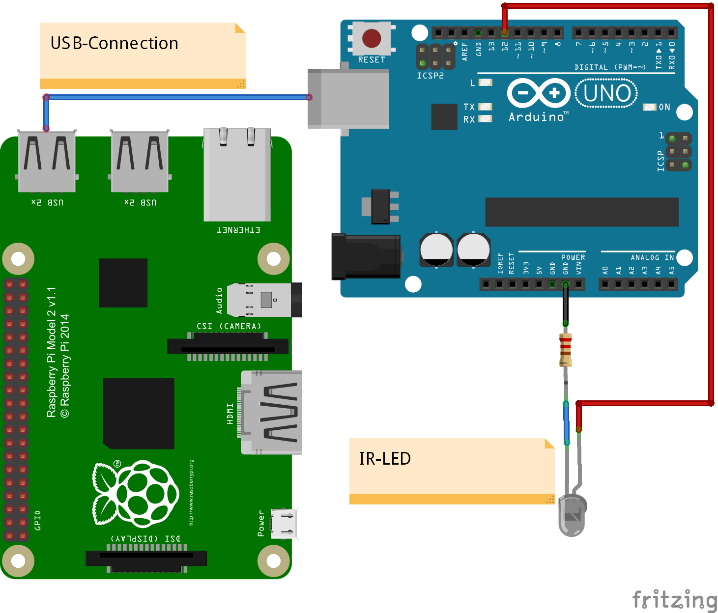
Arduino UNO has an USB connection, which supports serial connection to a host computer. The arduino can be used as a IO expander, connecting digital io lines, pwm, servo or adc-inputs directly to scratchClient and to scratch.
On digital inputs D2-D12, the firmware supports counters. The inputs are debounced  and frequencies are possible till prox 50Hz.

This setup with scratchClient can be run on Raspberry or on windows, unless scratch 1.4 is used.

Powered by the USB-connection, the UNO provides 5V-compatible inputs/outputs. This is an advantage in some constellations. But do not connect these outputs directly back to the raspberry GPIO pins. And be careful on power consumption. Small servo can be operated, but larger current devices need external 5V supply.

The solution is also applicable to arduino NANO. This small board offers a breadboard friendly layout.

nano_breadboard

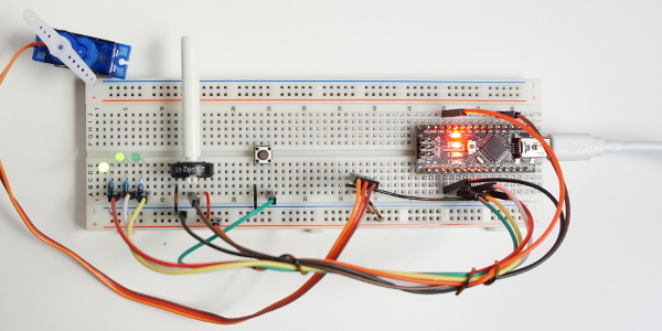
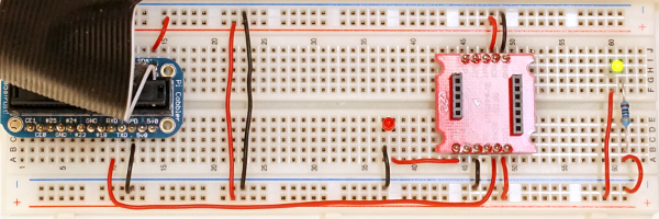
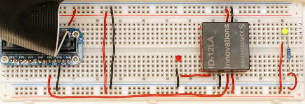
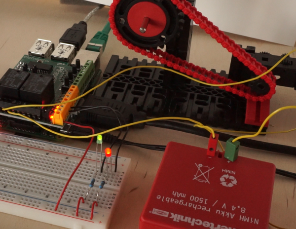
Sample setup with a NANO, 3 LED, Poti, Button, Servo and NANO on breadboard. Host computer (Raspberry Pi or Windows) not shown.

The functionality presented here is not a bridge to mesh network, propagating events and sensor updates into the arduino. There is a custom arduino sketch needed which only exposes the IO resources, but does not allow for additional logic in arduino (yet).

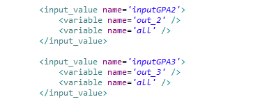
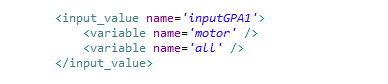
Configuration of the io-pins (direction, pullup, pwm, servo) and adc-pins (whether used or void) is controlled by scratchClient through configuration.
The scratch names used are configurable in configuration too. This is common functionality of the framework.

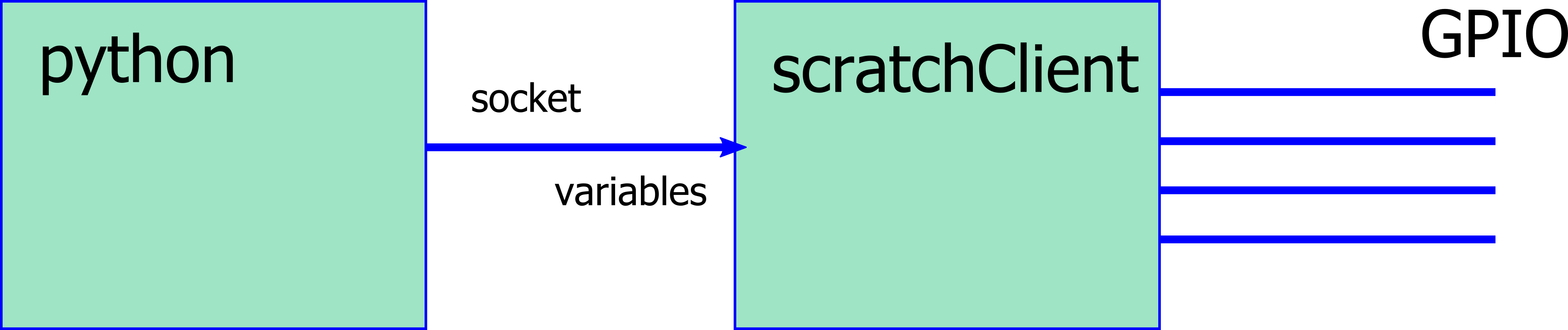
Communication between host computer and arduino is by a serial line USB connection.  Speed is 115200 bd, set line end to LF . The arduino protocol uses as short as possible command sequences.
Example:
pwm:4,90\n  sets PWM channel 4 to 90.
p:4,90\n is the same command, abbreviated.

With
help\n
a summary of command features can be printed.

The protocol is build on readable ascii sequences, which makes debugging with arduino serial monitor easy (set line end feature to ‘newline’). This also allows to fully drive the protocol from the serial console.

The command parser uses a state based approach for speed purpose. Each received char needs to be processed as quick as possible, which is only possible with a state machine.
First implementation was collecting chars in buffers and on a LF-char the data have been compared to the different commands. This needed many expensive strcmp-operations, decoding the parameters was done by sscanf. This approach limited throughput.

The parser code is generated by a python program and the resulting code is then inserted into the arduino C-program.

The code for arduino, sample configuration for scratchClient and sample scratch program is in the scratchClient distribution.

For setup, follow the steps described below.

Step 1, program the firmware to arduino

Start arduino IDE software, load arduino/arduinoUno/arduinoUno.ino from the scratchClient distribution and program it into the UNO or NANO. This needs to be done only once. I run this from a windows machine, but arduino IDE should also be supported on Raspberry Pi.

The LED13 on the arduino should blink at 5Hz, quite fast. This indicates that the firmware is running, but did not yet receive configuration.
On a serial monitor, you should see:

arduino sending@115200 Bd
arduinoUno, version 2016-02-21
config?
config?
config?

The config?-request is printed each second until the host provides configuration commands. Close serial monitor in order to allow scratchClient to have access to the serial line.

With ‘help’ from the serial monitor (use newline for line end separator), the arduino provides the list of supported commands.

Step 2, sample Hardware setup

arduinoUno_Steckplatine

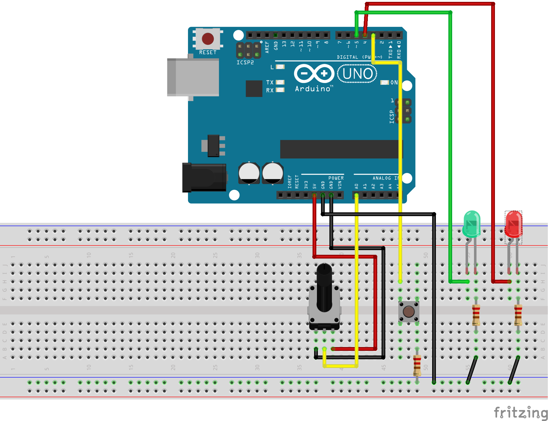
The hardware uses a potentiometer (2k to 10k are ok) on AD0. On D3, there is a button connected. The other side is having a 1k-resistor to GND (just in case the output is configured as an output, this prevents damage to the IO).
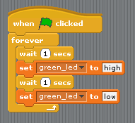
Two LED are for output. The green LED is on a PWM-output D5, so it can be dimmed.

This setup is a sample. The functionality of all the inputs and outputs are defined by configuration in scratchClient. See config/config_arduino_uno.xml for a sample.

Step 3, connect arduino with USB-Line to RaspberryPi or windows computer.

On raspberry, lookup /dev /tty* connections and configure the UNO serial device in config/config_arduino_uno.xml-File.

For windows, you see the COMn-Device used in deviceManager. Configure this name in config file.

An arduino UNO or NANO needs a few 20mA when running,  LEDs add prox 10mA each. This current is provided by USB port of host computer. If more power is needed, then an external power supply is needed.

Step 4, start scratchClient with configuration

cd ~/scratchClient
python src/scratchClient -c config/config_arduino_uno.xml

After a short while, the LED13 should start blinking at 0.5Hz, quite slow. This indicates that configuration was downloaded and system ready to be used. The Tx, Rx-LED on arduino should flash now and then. Quite often when you turn the potentiometer, or when you press the button.

Step 5, start scratch with sample program

There is a sample program in scratch/arduinoUno/arduino.sb

scratch

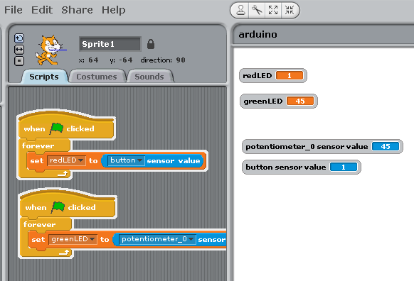
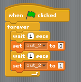
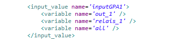
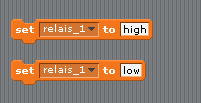
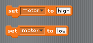
The program takes the button input and controls the red LED with it.
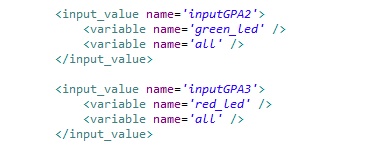
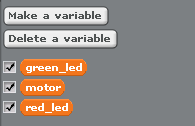
The value from the potentiometer is used to set the pwm-rate and dims the green LED. The mapping of the variable names or sensor names to IO-points is done in config file.

ID-Code

The arduino can have an ID-code in eeprom, which can be set by serial line console and read out from remote. This ID allows the host raspberry to recognize the arduino and provide configuration for this special device. This is a very nice feature for school setups where some experiments are hard wired and need fixed configuration. There is a starter code available which checks the connected arduino, and presents the related config files for scratchClient to start. I am working on an extension to start scratch with a basic program too. Avoids a lot of handling errors in school, especially where the focus is on driving an experiment and coding is not so important.

The serial protocol allows to read and set the ident code.

cident?\n     request idcode
cident:<char16>\n write idcode

Configuration Tool

The setup of the xml config file is not very intuitive. There is a config gui available to edit the file. The tool is started with

cd ~/scratchClient/tools
java -jar scratchClientConfig.jar

scratchclientconfig

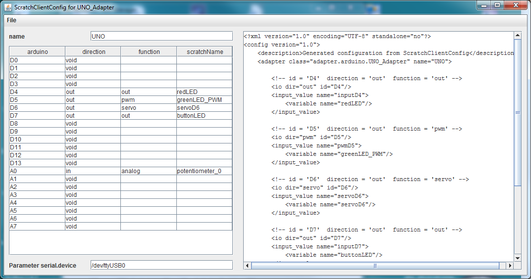
The left side of the frame is the editor pane which allows to select the various functions for the arduino. The right panel is a view-only display of resulting xml data.

Existing files can be loaded, but current version (2017-02-10) only allows to handle one adapter of type ‘UNO_Adapter’.

Constraints

The adc-channel is limited to 10Hz update rate. There is averaging for three samples per measurement value transmitted.
The digital inputs are limited to 20Hz update rate.
The adc-channel of atmel328 allow for analog inputs or GPIO usage.
PWM pulses are created with arduino native analog_write on the digital pins. Value range for pwm are 0..255.
Servo pulses are created with Servo-library. See limitations of this library in Arduino Servo [https://www.arduino.cc/en/reference/servo]. Input values for servo are 0..180.
Configuration is not persisted in the arduino (but downloaded from the the scratchClient adapter); there is no interface for custom logic (for fast sensors).
Configuration is requested to be sent from PI or windows to arduino on reset of arduino. If scratchClient configuration is changing, then a reset of arduino is needed to make this active. As in most cases a hardware change is made with arduino disconnected from power (either USB cable or power plug), this is only a small limitation.

This scratchClient adapter runs also on windows platform. This allows setups where a windows computer, scratch 1.4 for windows are using IO connections.

Other libraries

Recently I discovered ‘nanpy’, a python library to control an arduino by python programs.

Updates

Updated 2017-03-15, Counter for digital inputs added.
Updated 2017-02-10, Config tool for xml config file included.
Updated 2016-02-21, Some remarks on state based parser, command sets.
Updated 2016-02-15, added servo capability.

scratchClient and piGlow

piGlow is a nice little board, providing 18 colored LED with an I2C-Controller.

With a major rework of the i2c-part of the scratchClient framework, I added support for this board / device in scratchClient.

Start it with

cd ~/scratchClient
sudo python src/scratchClient.py -c config/config_SN3218.xml 

The configuration uses some common variables to update the pwm-values in sync for all, for the ‘branches’ and – of course – the individual LED.
In the distribution, there is a simple scratch program, just providing variable definitions and some watchers on stage with sliders.
piglow_scratch

Not very graphic, I agree. But hopefully it saves some time in creating these 18 variable names (plus some more). It is in scratchClient/scratch/SN3218/piglow.sb

The branches are group names for the three wings arranged on the board.

piglow_annotated

The above sketch shows the piglow board in action, annotated with the channel numbers in hex.

As indicated on the package of piGlow, the LED can be VERY bright when full power is applied. Looking into these light could harm your eyes.

But there is a trick to project an image of the LED to a remote screen (or the ceiling of my room).
Use a magnifying glass or an objective lens.
lupe

When adjusting the setup, be sure NOT to have the LED at full brightness.

aufbau

Place the lens in the correct distance in front of piGlow. I first tried out which distance is needed by hand, and then fine tuned the focus by adding sheets of paper. It was needed to place the lens in a stable position for the photograph.

result
The result on the ceiling, prox 0.3m large, 1.6m away. The dark grey structured background is the white ceiling, outshined by the image of the LED.

The center LED are opaque, the other LED show the bright chip inside the small package. The image in this setup was 15 times enlarged.
Again: never look into the bright light directly.


scratchClient and piFace

piFace uses MCP23S17-chip, which is supported by scratchClient.

The chip is a 16bit port expander; in piFace one group is used as an input, the other group of 8 bits are used as outputs, connected to a open collector driver.
One of the interrupt pins of the chip ‘intB’ is connected to  GPIO25. This is not used by scratchClient (but does not allow to use this pin for other purpose.

The hardware setup: two LED, a green one and red one, and a small motor powered by a battery and controlled with the relais.

hardware

This post demonstrates the use of scratchClient as a ‘hardware abstraction layer’, assigning meaningful names to scratch variables.

In this example, I connected a red and green LED to piFace.
With default configuration, the default names are ‘out_2’, ‘out_3’.

config_default

Here a sample of a blinking LED, using these definitions.

script_default

This works, but the variable names are not very conclusive. There is the need to keep a record on what this ‘out_2’ is meaning. But scratchClient allows to tweak the configuration files and provide more meaningful names for the variables controlling the hardware.

When editing scratchClient/config/config_mcp23s17.xml, the names of the variables in scratch can be changed. ‘green_led’ and ‘red_led’ are better describing what is connected to the hardware.
config_renamed

Restarting scratchClient is needed when configuration is changed.

Side topic: the ‘all’-variable, common to all outputs here, can be used to set all values immediately to either ‘0’ or ‘1’. Useful for a ’emergency shutdown’ or alike.

With the meaningful names, a scratch script looks like this:
script_renamed

The script gets more expressive. There is no need to map the abstract names to the thing connected.

Another example. Suppose a small motor is connected to relais_1.config_relais

Here, the variables ‘relais_1’, ‘out_1’, ‘all’ can be used to drive this output.

Setting this variable is straightforward, but ‘relais_1’ is not a descriptive name.

script_motor

When editing the configuration, the scratch variable names can be changed to ‘motor’.

config_motor

This changes the names in scratch to  ‘motor’.

script_motor_renamed

The following snippets show the changes: left side are the default definitions, right side the more meaningful names.

variables_default variables_renamed


Smartphone positional sensors connected to scratch

In a quite popular computer magazine, c’t 2015-03-07 (heise verlag), there is a nice article about how to connect a smartphone’s positional sensors to a remote server by using a web page, some javascript and websockets.

Starting from this, there was the idea to connect this to scratch (what else ?).

The basic roadmap was
– add a html-page to my scratchClient’s web server, with javascript

var addr = "ws://" + window.location.hostname + ":" + window.location.port + 
           "/pendel";
var websocket = new WebSocket( addr );
 
function handleOrientation(event) {
       var x = event.beta%90;
        var y = event.gamma;
        x += 90;
        y += 90;
          try {
                websocket.send(JSON.stringify( { x:x, y:y }));
            }
            catch(err) {
                // console.log( err.message );
            }
    }
    window.addEventListener('deviceorientation', handleOrientation);

– in scratchClient, there is cherrypy used to serve the web pages. WebSocket was a new feature to be added there.

– an adapter needed to be written adapter.websocket.WebsocketXY_Adapter, receiving the messages and converting them to scratch variable updates.

So far the plan.
Websocket implementation in sandbox environment worked well, but as I use ‘routes’ to dispatch the requests it took some time to find the correct setup.
Next finding was that the connection is really performant, and a slow movement of about a second duration provides a hundred messages flowing into scratchClient. This is far above from what scratch is able to handle.

Filtering out messages is starting in the browser. Rounding values to a tenth of a degree and sending values only on change removes quite a lot of values. After some experiments with timers in my android browser I found no viable solution to throttle update rate. Timers seem not to work in this javascript environment. Next step in filtering is in the adapter, taking most current value each 0.05sec and ignoring intermediate values.
Final step of filtering is inside scratch. When using the ‘glide’-move, scratch will ignore intermediate values. When using the ‘goto’-statement, processor load is getting much higher.

When I have seen webSocket working pretty smart, I removed the ajax-updates and webEvents from/to web browser to server. When working on the server side, some legacy code in editing values in browser was rewritten, the svg-generator is smarter now and the underlying event distribution system in scratchClient was replaced by a publish-subscribe pattern.

Installation of scratchClient now needs ‘ws4py’ in addition to cherrypy. See the docs.

Start scratchClient

cd ~/scratchClient
sudo python src/scratchClient.py -c config/config_websocket_pendel.xml -guiRemote

The guiRemote-switch is needed to allow remote browsers connecting to scratchClient.

In a smartphone browser, navigate to your pi’s address. Of course you need a (wireless) network connection between smartphone and raspberry. In my network, the RaspberryPi’s address is 192.168.2.90, most possibly different for your PI. Use ‘ifconfig’ to look it up.

http://192.168.2.90:8080

Navigate to “Smartphone as Sensor” browser

You should see rectangle with a red/green dot moving around. This is as proposed by the c’t-article.

In scratch, enable remote sensor connections and provide the following script. gotoX and gotoY are sensor values provided by the scratchClient. The xl and yl-Variables are local variables in scratch.

smart

The x and y-values are getting exchanged and the y-value gets inverted to match the coordinates of the smartphone to scratch stage.

And thats it. The sprite moves close to the smartphone movements. There is some small time lag on my PI ModelB (not a pi plus so far), but sufficient good.