Category Archives: scratchClient

scratchClient related things

Timer for HC-SR04 ultrasonic sensor and scratch

The ultrasonic sensor HC-SR04 is a quite inexpensive ultrasonic sensor, well suited for microcontroller applications.
It produces pulse width modulation directly giving the signal run time.

For 1.7m, at sound speed in air of 340m/s, you get 10ms pulse width.
Up to now, my scratchClient software had no ability to support this device. In order to evaluate different approaches to measure pulse width timings in this range, I have set up an arduino board simulating this device with 10ms timing.
The goal was to have around 1000 measurements and look for the distribution of values.

Approach A was to take python code as found on the net. Two loops, first one looking for raising pulse and second one looking for falling pulse.

python
Results are not very precise.
There are quite a lot of measurements at 10ms, but 2/3 of all results are up to 40% higher; few also till 16,5 ms. This is as expected, as the IO system is slow, and a lot of other things are running in the system in parallel.
Advantage is that there are no additional cost, except some voltage dividers needed.

Approach B is a microcontroller subsystem using the atmel 328 chip, sitting on a breadboard and connected with SPI to RPI. The internal oscillator is used for simplicity and reduced cost. This setup is similiar to the adc-setup described in another post.
Time measurement is using the 16 bit timer in 1/64 resolution, yielding 8us values.

ultrasonic_328
Results are pretty nice, although the deviation is 3% from 10.0ms. Most possible this is caused by the free running oscillator running a little bit too fast; some more investigation is needed here to eliminate software errors.

The code is polling the timer, which is fast enough for this application. SPI is handled with an interrupt coded in assembler. This allows up to 240kHz SPI frequency.
The software is completed and supports up to 4 sonic sensors.
Cost is prox 3.5$ per unit, some soldering and some voltage dividers. No difficult software setup needed.

I found other approaches on the net. DMA code, C-Code or alike. Problem here is the complicated software setup (no ready to use solutions) and the difficult integration into the python environment with RPI.GPIO.

The hardware setup is straightforward. Note the 5V on the supply voltage of the HC-SR04. Doublecheck also the ground connection from HCSR04 to breadboard and to Raspberry. This is important to avoid to get 5V into the raspberry inputs.

For the scratch setup, there is a sample configuration with device(0) connected.

cd ~/scatchClient
sudo python src/scratchClient.py -c config/config_hcsr04_atmel328.xml

In scratch, enable remote sensor connections. You receive ‘distance_A’.

For detailed instructions on how to program the atmel processor, see the documentation in the download file on download page. The programming is performed by the raspberry pi with the SPI cabling.

MCP23S17 aka piFace supported in scratchClient

The 23S17 is the chip used on piFace, It can be used also on a breadboard, providing 16 extra IO-pins for the raspberry.
The adapter adapter.mcp23s17.MCP23S17_Adapter expands the IO-capabilities by 16 ports, either input or output.

 mcp23s17

On the image you see the breadboard setup with the device 23s17, connected with an adafruit breadboard adapter to raspberry pi. The small boards plugged in vertically contain 8 LED with a resistor array. I use those whenever I need more than one LED on a setup.

Programming details

This adapter was a challenge. It needed a configuration specific for each adapter instance of this type, and this complexity was beyond the available <parameter/>-tags. The decision was to break the configuration phase into multiple steps, where after basic creation and setup of the adapter instance the configuration manager passes control to the adapter and provides the local xml config node in this call. The adapter reads the <io/>-tags, configures the necessary adapter methods for sending and receiving variables and gets the device settings for input, output direction and pullup setup.

Configuration details

The device 23s17 allows to have up to 8 devices ‘in parallel’ on one SPI chip select. These devices have hardwired distinct slave addresses. In the configuration, this slave address must be given.

        <parameter name='spi.bus' value='0' />
        <parameter name='spi.device' value='0' />
        <!-- slave address must match the hard wired slave address on the device -->
        <parameter name='23s17.addr' value='0' />

The IO direction for the port pins is defined by <io/>-tags.

        <io id='GPA0' dir='out' />
        <io id='GPA1' dir='out' />
        <io id='GPA2' dir='out' />
        <io id='GPA3' dir='out' />

        <io id='GPA4' dir='out' />
        <io id='GPA5' dir='out' />
        <io id='GPA6' dir='out' />
        <io id='GPA7' dir='out' />

        <io id='GPB0' dir='in' pullup='none'/>
        <io id='GPB1' dir='in' pullup='none'/>
        <io id='GPB2' dir='in' pullup='none'/>
        <io id='GPB3' dir='in' pullup='none'/>
        
        <io id='GPB4' dir='in' pullup='weak'/>
        <io id='GPB5' dir='in' pullup='weak'/>
        <io id='GPB6' dir='in' pullup='weak'/>
        <io id='GPB7' dir='in' pullup='weak'/>

It is generally a good idea to define all of the port pins. Technically it is needed to define those which are used in the application. The id-values are predefined and must be used as seen here.

For ports defined as dir=’out’ outputs, the corresponding adapter input methods can be used:

        <input_value name='inputGPA4'>
            <!-- variable name is the name of the scratch variable which is 
                 send out to the adapter -->
            <variable name='input_4'/>
        </input_value>

For ports defined as dir=’in’ inputs, the corresponding adapter output methods can be used:

        <output_value name='outputGPB2'>
            <sensor name='output_2'/>
        </output_value>

The variables send out from scratch are ‘0’, ‘1’ to set the output pin of the 23s17 to low, high.

The sensor values received from scratch are ‘0’, ‘1’ for the input pin of the 23s17 receiving low, high.

Start scratchClient

scratchClient startup does not need special considerations.

cd ~/scratchClient
sudo python src/scratchClient.py -C config/config_mcp23s17.xml

The file config/config_mcp23s17.xml is an example of a full functional configuration.

Barcode scanner for scratch

barcode

Connecting a barcode scanner to scratch

Some time ago I aquired a barcode scanner, which I use to manage a CD collection based on the EAN-code printed on the packages.

These scanners typically can send codes by emulating HID-class devices. This makes usage from programs quite easy, but you loose input when the program goes to background and other programs get the focus.

Currently I try to bring this code to raspberry pi, using python and pyusb library. This library allows access to usb devices and, very important, can grab devices to be used exclusively by one program. As a side result from this work, I added a barcode scanner adapter to scratchClient.

Install pyusb

Here I found a problem. The usual install did not workwith „pip install pyusb“. This resulted in a ‘backend not found’ exception and „undefined symbol: libusb_strerror“
When I tried to download walac-pyusb-50b1490 from https://github.com/walac/pyusb, this worked, but I had to uninstall the pip-installed code first „sudo pip uninstall pyusb“.

The needed backend packages are already available in raspbian, you can check this with

apt-cache pkgnames | grep libusb

You should find libusb-1.0-0 in the list.

Setup Scanner for USB and CR-suffix

A few preparations are needed with the scanner to enable HID mode. With my scanner I got a handbook with a huge amount of programming codes. You start programming with a ‘start programming’ code, scan the appropriate setup code and exit programming with an ‘end programming’ code.

For my sample, I have setup HID mode, and added exit code/suffix CR. This is needed to detect complete sequences. The adapter in scratchClient relies on this.

Configure idVendor and idProduct

Another preparation is the configuration of idVendor and idProduct in the adapter’s config file. Use the utility enum.py to list the devices available

cd ~/scratchClient
python tools/usb/enum.py

Here the output for my scanner

DEVICE ID 0c2e:0200 on Bus 001 Address 007 =================
bLength : 0x12 (18 bytes)
bDescriptorType : 0x1 Device
bcdUSB : 0x110 USB 1.1
bDeviceClass : 0x0 Specified at interface
bDeviceSubClass : 0x0
bDeviceProtocol : 0x0
bMaxPacketSize0 : 0x8 (8 bytes)
idVendor : 0x0c2e
idProduct : 0x0200
bcdDevice : 0x5881 Device 88.81
iManufacturer : 0x1 Honeywell Scanning and Mobility
iProduct : 0x2 Honeywell Scanning and Mobility Scanner
iSerialNumber : 0x0
bNumConfigurations : 0x1
CONFIGURATION 1: 300 mA==================================
bLength : 0x9 (9 bytes)
bDescriptorType : 0x2 Configuration
wTotalLength : 0x22 (34 bytes)
bNumInterfaces : 0x1
bConfigurationValue : 0x1
iConfiguration : 0x3 HID Keyboard
bmAttributes : 0x80 Bus Powered
bMaxPower : 0x96 (300 mA)
INTERFACE 0: Human Interface Device ====================
bLength : 0x9 (9 bytes)
bDescriptorType : 0x4 Interface
bInterfaceNumber : 0x0
bAlternateSetting : 0x0
bNumEndpoints : 0x1
bInterfaceClass : 0x3 Human Interface Device
bInterfaceSubClass : 0x1
bInterfaceProtocol : 0x1
iInterface : 0x0
ENDPOINT 0x81: Interrupt IN ==========================
bLength : 0x7 (7 bytes)
bDescriptorType : 0x5 Endpoint
bEndpointAddress : 0x81 IN
bmAttributes : 0x3 Interrupt
wMaxPacketSize : 0x8 (8 bytes)
bInterval : 0xa

What you also should check is the iConfiguration to be a HID Keyboard.

For verification open a text editor like leafpad: when scanning a code, this should be entered into the editor as a text string.

Edit config/config_barcode.xml and adjust the vendor/product id there.

In my environment, I use a powered USB hub to connect the scanner.

Start scratchClient

cd ~/scratchClient
sudo python src/scratchClient.py -c config_barcode

The file config/config_barcode.xml is a starting point for a project. Add other adapters as needed.
When scanning barcodes, these are send to scratch. Do not forget to enable remote sensor connections.

scratch_barcode

Environmental Sensors for scratchClient

The recent months have been busy with preparing new experiments for my
school project, especially one experiment measuring temperatures with TMP36. See
link

When looking in detail to the datasheet of TMP36, there is an accuracy of max
+- 4K (G-Grade device) and +- 3K (F-Grade device). This is not bad for -40 to 125 °C. At 25°C, accuracy is  +- 3K (G-Grade device) and +- 2K (F-Grade device).
Unfortunately the ADC on my adapter board, the MCP3202, uses the
vcc-voltage as reference, which gives additional error for the measurement.
With patch cables, there is also some noise. I twisted signal and ground
line, added some capacity close to the TMP36 power pins and a low pass
filter in the adapter logic. Which reduced, but did not remove the problems.

So I started to look for more precise alternatives. LM35 in combination
with an adc ads1015 and internal precision reference voltage gives better results.
LM35A specs give +-1K over -40 to 110 °C, around 25°C +- 0.5K.

When starting to look for integrated solutions, complex devices like SHT15
come around. Main purpose is to measure humidity, but temperature
measurement is included. +-0.3K around 25°C and +-1.5K in -40 to 90°C are
quite good. I2C is not supported, but a two-wire GPIO protocol is
available. Disadvantage is the high price.

BMP085 is a digital pressure sensor with temperature sensing included. +-2K
accuracy in 0 to 65°C. I2C, internal calibration data in registers, needs
some calculations to correct the raw values.

MAX31855K is used with k-type thermocouples and extends temperature range
to -200 to 1350°C. Note that K thermocouples have about ±2°C to ±6°C
accuracy. SPI interface is easy to use.

And for curiosity, I added a luminosity sensor BH1750 to this collection of
devices.

Scratch integration is ‘as usual’ with adapters, where configuration is
done by xml files.

Hardware interface to the devices (to be more precise: the breakout boards
with the devices, is by I2C, SPI or plain GPIO. For the SHT15, I added a
serial resistor of 1kOhm for the data line to protect against
input-output-mismatches during debug phase of code. For the clock line, this
is not needed, but in general a good idea to a serial resistor there too.
Too expensive this device, to take the risk of burning it away.

These sensors will not be part of the school workshop documentation. Setup
is described in the scratchClient handbook → link.

Sending, Receiving SMS messages with GSM Modem

Recently I bought an instance of adafruit’s SIM800 breakout board ‘fona’. This board allows for sending and receiving of SMS  text messages (and a lot of other functionality, of course. But I covered only the text messages for scratch). For the text messages, I added an adapter for my scratchClient software.
For download and documentation, see [url]http://heppg.de/ikg/wordpress/?page_id=6[/url]

In scratch, a variable ‘sms_out’ is used to send messages, incoming messages are in the sensor value ‘sms_in’. Easy to use, and today I ignored provider cost and have sent me SMS every hour ‘scratch installation still running’. Could be more useful, but is fun when your computer gives you a call.

Connection of fona is by RX, TX to TX, RX of raspberry. You need to remove some getty processes from this line, there are documentations around describing this.

The sim800 uses an AT-protocol, like ‘at+cpin?’, and receives signals like ‘+CPIN: SIM PIN’.
For the initialization of the device, the adapter implements a state machine, which step by step initializes the modem, sets the pin and then waits for action.
Switching the modem on is done by pressing the ‘on’ key on the breakout board. Could be done by using GPIO, but I decided to need some additional access control.

The receiver side oft the serial protocol reads line by line, looks for known names and feeds the state machine with input.

The code is still experimental. There is no buffering for scratch input, so if scratch feeds too fast, there will be lines dropped. But It is not intended as a spam machine… The phone number being called on send events is fixed for the same reason.

If you want to run the software, be sure to have a backup phone which allows to reset the pin (in case it was forgotten to configure the pin in the adapters xml file, it might happen that after a few retries the device is blocked.)
And the manual of the sim800 is useful. Which is 300 pages.


Scratch Connection Status Display

With a new adapter adapter.gpio.GpioStateOutput, it is possible to bring the scratch connection state to GPIO.

When scratchClient is started, the associated GPIO pin is going high. When connection to scratch is established, the pin is blinking slowly. And when scratchClient is terminated, the GPIO is going low.
Just add the configuration für this adapter to your configuration.

    <adapter class='adapter.gpio.GpioStateOutput'  name='state'>
        <description>State display on IKG.IO.9</description>

        <gpio port='IKG.IO.9' alias='state'>
            <default dir='OUT'  default='low' />
            <active  dir='OUT'  default='low' />
        </gpio>
    </adapter>

Please note the naming of the port: these names are configurable. You could use GPIO04 instead, or P1-07 if you prefer board numbering.
For my school workshop, there is an extra LED available, connected all the time, but not used for other IO. This LED sits on the adapter board in a corner and is ideally suited for a state display.

Atmel atmega328 used as AD-Converter for Raspberry Pi

[german]

see also: Arduino UNO, NANO connected to Scratch

Atmel 328-Prozessor used as AD-Converter

The microcontroller ATmega328P in DIL-package can be used on a breadboard.

This controller has many build-in functions, as ADConverter, timers SPI and more.
The Arduino boards use this controller, making it very popular and many literature is available.
The ADC has 10Bit resolution and in DIP package there are 5 channels available.

Wiring to Raspberry Pi is quite simple. The firmware can be programmed directly from RPi, no programming device needed. The focus of this article is not the programming of the device. The needed firmware is attached to the samples.
Cost of the devive are comparable to simple ADConvertes and are about 4€.

Disadvantage is the more complex setup needed.

On the download page, I provide a firmware which can read two AD-channels and to control a LED. More functions are planned, as frequency measurement, infrared control or rotary encoders.

The firmware of the controller can be programmed with the RPi. No extra flashing hardware is needed.
Prerequisite is that the controller has the internal 8MHz oscillator enabled. This is factory preset.
Basic setup of the controller is defined by ‘fuses’, especially the setup of the oscillator used. Without a working oscillator, programming is not possible.
If you get an already flashed device, e.g. prepared to be used in an arduino board, these will have internal oscillator shut off. In this case, reading out the software will not work. Workaround is to activate GPIO#4 of RPi as a clock source and connect to the 328. See attachments for a short tutorial. Or to use a flashing hardware.
Caution: when you use a device from an arduino board it is likely that the bootloader is overwritten. There is no simple way back.

parts list

  • ATmega 328 P-PU (DIL-package)
  • breadboard
  • precision socket for the processor. DIL 28 pin, 0.3 wide. Insert the socket to the breadboard, and insert the controller into socket. The controller can be used directly, but with the socket insertion and removal is simpler.
  • LED. The longer wire is the anode and is the ‘positive’ side.
  • resistor 1kOhm
  • capacitor ceramik 100nF, min 10V
  • trim potentiometer for test
  • cables f-m, 7 or 8 pieces
  • wires for breadboard.

Setup procedure

Basic steps are wiring, flashing the controller and activating scratchClient software.

electrical setup

Shut down RPi and disconnect power source.

Place processor on breadboard and connect according to scheme.

VCC 3.3V is taken from from Raspberry.
SPI-connections MISO, MOSI, SCK and SS at CS0 of RPI allow communication.
RESET pin 1 to GPIO24 is needed for flashing in addition to SPI.
LED with serial resistor 1kOhm is connected to PB1, Pin 15atmel_Steckplatine.
ADC-inputs used are ADC0 and ADC1, Pin 23, 24.

Prozessor im Sockel

This is how the controller sits in socket on breadboard.


Installing flash software on Raspberry Pi

sudo apt-get update
sudo apt-get upgrade -y
sudo apt-get install python-dev pip
sudo pip install spidev intelhex

Activate SPI driver. Use raspi-config , enable SPI.

Copy the programming software to /home/pi .

Download software and store in /home/pi and unpack “tar xfvz program_328.tar.gz”.

tar xzvf program_328.tar.gz

Validate hardware and software setup

The following steps validate correct cabling and whether flashing the controller is possible.

Read Fuses

cd ~/program_328
sudo python src/program.py -rf

The output should look similiar to

PROGRAMMING_READ_CALIBRATION_BYTE b0 10110000
 PROGRAMMING_READ_EXTENDED_FUSE_BITS ff 11111111
 BODLEVEL0 1
 BODLEVEL1 1
 BODLEVEL2 1
 PROGRAMMING_READ_FUSE_BITS e2 11100010
 CKSEL0 0 ENABLED
 CKSEL1 1
 CKSEL2 0 ENABLED
 CKSEL3 0 ENABLED
 SUT0 0 ENABLED
 SUT1 1
 CKOUT 1
 CKDIV8 0
 PROGRAMMING_READ_FUSE_HIGH_BITS d9 11011001
 BOOTRST 1
 BOOTSZ0 0 ENABLED
 BOOTSZ1 0 ENABLED
 EESAVE 1
 WDTON 1
 SPIEN 0 ENABLED
 DWEN 1
 RSTDISBL 1
 PROGRAMMING_READ_LOCK_BITS ff 11111111

If there are errors (Device not in sync), then either cables are not correct connected or the processor has wrong fuses already programmed.
Check connections. If error persists, then connect external clock.

Read out current code

Another step in validating the setup is to read current code. Should be empty on a brand new device, but is useful to check communication.

cd ~/program_328
sudo python src/program.py -r

The output should look similiar to

python src/program.py -r
 ('read', 'out.hex')
 programming_readCode
 programming_enable
 ('PROGRAMMING_ENABLE', [172, 83, 0, 0])
 (0, [255, 255, 83, 0])
 programming_enable end
 programming_disable
 programming_readCode ende
 ok

Flash testcode to controller

When everything went smooth so far, then it is time to load the first testcode into the controller. It dies nothing but let the LED blink.

cd ~/program_328
sudo python src/program.py -p 328/steckbrett_328_blink.hex

LED should blink slowly.

Program Fuses for oszillator

The controller runs with internal oscillator, but frequency is limited to 1MHz. By setting the correct fuses, the Controller runs with 8MHz.

Please do not program the fuses, if there have been errors in steps before (which are not yet fixed) and the LED is blinking.

cd ~/program_328
sudo python src/program.py -wf

Blinking should stop shortly, and restart quicker, 5 times a second.
Oscillator setup is completed now.

Flash firmware to controller.

Final step is flashing the application firmware. It handles the AD-Conversions, LED-Settings and alike.
cd ~/program_328
sudo python src/program.py -p 328/steckbrett_328.hex

After programming is complete, the LED should blink 8 times. This is part of the RESET routine.

Application – testcode

Blink the LED, long bright, short dark.
cd ~/program_328
sudo python src/test_blink.py

The duty cycle is set by the python code in side Raspberry. This indicates that it is the reaspberry having control.

Read firmware version.
cd ~/program_328
sudo python src/test_get_version.py

Display should show ’93 09′; second number is minor version and can be higher.

Read ADC, Channel 0
cd ~/program_328
sudo python src/test_adc_0.py

Scratch-Connection

When tests for application software work, the next step is the connection to scratch.

cd ~/scratchClient
sudo python src/scratchClient.py -config config/config_adc_atmel328.xml

Configuration can be adjusted in the config file. ADC-channels can be enabled / disabled, or reference voltage can be 3.3-V or the internal reference 1.1V.
The internal reference voltage is useful when an tempperature sensor TMP036 is connected.
The 3.3V-reference is perfect when a potentiometer is connected.

The ADC values are sent with variable names ‘adc_0’ und ‘adc_1’ to scratch, range is 0..1023.
Broadcast commands from scratch to controller are ‘led_off’, ‘led_on’.

SPI-Communication between RPi and Controller

SPI is a synchronous protocol. The Controller as slave has no chance to indicate ‘slower please’ to the master. Therefor, each command from RPi to controller needs to be answered in the time between receiving the first an second byte of a sequence. Otherwise, there will be garbage read back.

This limits transfer speed to 240kHz with the 8MHz controller. With the 20MHz variant, this will be faster.

Appendix: GPIO#4 of RPi as clock-input for 328

Der GPIO#4-Pin can be configured to provide a MHz range clock signal for the controller. The program for this is in bin/-folder. It is based on code from guzunty.org.

Connect GPIO#4 with XCLK-Eingang of controller. Then start program bin/gz_clock_1.92MHz.

cd bin
chmod +x gz_clock_1.92MHz 
sudo ./gz_clock_1.92MHz

While this program is running, execute read/write of fuses in a second terminal window.
Then disconnect GPIO#4.

Update history:
2014-04-01 Fixed connections of LED

Capacitive Sensor for Scratch

[german]
Using an oscillator and a microcontroller atmega328 it is possible to build a fill level measurement for scratch, based on a capacitive sensor.

The controller is measuring the frequency of the oscillator. Data are transmitted by SPi to raspberry. A scratchClient adapter is calculating the frequency and forwarding them to scratch.

The video shows the setup on breadboard. Left side is the oscillator, in the middle is the controller and then the connection to raspberry. The sensor is build from a stripe of copper coated epoxy, separated in the middle. As air has different electrical characteristics than water, the capacity of the capacitor changes close to water. An oscillator, using this capacitor, will change its frequency.

atmel_Steckplatine

The scratchClient uses the adapter ‘Atmel328_ADC_Adapter’. The firmware is the same as for the ADConverter  AD-Wandler.

The oscillator ist standard TLC555, the cmos cousin of popular 555. The frequency range is in the example 13,5kHz in dry air and 9,6kHz with water in glass.

Frequency measurement is done in controller on 10ms or prox 72 periods. The controller is averaging the last 16 measurements. The ‘open’ construction causes some disturbances, causing sporadic measurement failures.

Update history:
2014-04-01 Fixed connections of LED

Kapazitiver Sensor für eine Füllstandsanzeige

[english]

Mit einem Oszillator und einem Microcontroller ATMega 328 kann ein Füllstandsanzeiger für Scratch gebaut werden.

Der Microcontroller ermittelt die Frequenz des Oszillators. Die Daten werden über SPI an den RaspberryPi gegeben. Der Scratch Adapter wertet diese aus und gibt sie an scratch weiter.

Der Film zeigt den Aufbau auf dem Steckbrett. Das enthält den Oszillator links, in der Mitte den Controller und dann die Verbindung zum RPi. Der Sensor ist ein Streifen einer Epoxydplatine. Die Kupferschicht wurde längs unterbrochen, so dass die zwei Platten eines Kondensators entstehen. Da Luft andere Eigenschaften als z.B. Wasser hat, verändert sich die Kapazität des Kondensators in der Nähe von Wasser. Ein Oszillator, der diesen Kondensator verwendet, wird seine Frequenz verändern.

atmel_Steckplatine

Der scratchClient benutzt den Adapter ‘Atmel328_ADC_Adapter’. Die Firmware des Controllers ist dieselbe wie für den AD-Wandler.

Der Oszillator ist ein TLC555, die CMOS-Ausführung des bekannten 555. Zusätzliche Bauteile sind 2 Widerstände 1M Ohm und ein Kondensator 100nF. Frequenzbereich ist im Beispiel etwa 13,5kHz ohne Wasser im Glas und 9,6kHz mit Wasser.

Die Frequenzmessung erfolgt im Microcontroller über ca 10ms bzw 72 Signalperioden. Die Werte werden auf dem Controller mit den letzten 16 Werten gemittelt. Wegen des offenen Aufbaus gibt es einige Störgrössen, die ohne Mittelwertbildung/Filterung sporadische Ausreisser produzieren.

Update history:
2014-04-01 Fixed connections of LED

Atmel 328-Prozessor als AD-Wandler für Raspberry Pi

[english]

Siehe auch
MCP3202-AD Wandler am Raspberry PI
ADS1015 als AD-Wandler am Raspberry Pi
Arduino UNO, NANO connected to Scratch

Atmel 328-Prozessor als AD-Wandler für Raspberry Pi

Der Microcontroller ATmega328P im DIL-Gehäuse kann auf dem Steckbrett in Betrieb genommen werden.

Der Microcontroller hat viele eingebaute Funktionen, wie z.B. AD-Wandler, Timer, SPI und anderes mehr.
Dieser Microcontroller ist im Hobbybereich sehr bekannt, da die Arduino-Boards mit diesem Microcontroller arbeiten.
Der AD-Wandler des Microcontrollers hat eine ausreichende Auflösung mit 10 Bit und es können bis zu 5 Eingänge angeschlossen werden. Damit kann er als Ersatz für einen AD-Wandlerbaustein benutzt werden.

Der Controller ist einfach an den Raspberry Pi anzuschliessen und sein Programm kann vom RPi aus aufgespielt werden. Wie der Baustein programmiert wird soll hier nicht beschrieben werden. Das benötigte Programm ist bereits übersetzt in den Beispielen enthalten.
Die Kosten für den Prozessor sind mit einigen Euro etwa so hoch wie für einen AD-Wandler.

Nachteil ist die etwas komplizierte Inbetriebnahme. Die ist deshalb so lang geworden, da viele einzelne Schritte und Überprüfungen aufgenommen wurden.

Das interne Programm des 328-Microcontroller ist in den Beispielen enthalten.

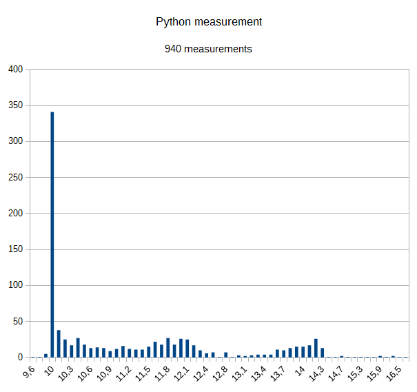
Das Programm kann zwei AD-Kanäle auslesen und eine Leuchtdiode ansteuern. Weitere Funktionen sind in Planung, wie ein Frequenzmesser, ein Anschluss für eine Infrarotfernsteuerung und Drehencoder.

Das Programm des Microcontrollers kann mit dem Raspberry in den Controller übertragen werden. Es ist also kein extra Programmiergerät erforderlich.
Voraussetzung ist, dass der Microcontroller den internen 8MHz RC-Oszillator aktiviert hat. Das ist bei fabrikneuen Microcontrollern der Fall.
Die Grundeinstellung des Microcontrollers, also auch die Steuerung der Oszillatoren wird über ‘Fuses’ eingestellt. Damit kann man den interen Oszillator aktivieren oder es werden Quartz-Oszillatoren oder eine externe Taktquelle aktiviert. Das Problem ist, dass ohne aktiven Oszillator das Programmieren mit dem RPi nicht funktioniert.
Falls man einen bereits programmierten Prozessor erhält, dann kann dieser den internen Oszillator abgeschaltet haben. In diesem Fall funktioniert bereits das Auslesen der ‘Fuses’ nicht.
Dann braucht man entweder ein spezielles Programmiergerät oder muss den GPIO#4 als Taktquelle aktivieren. Eine Anleitung dazu ist am Ende des Artikels zu finden.

Einkaufsliste

  • ATmega 328 P-PU (DIL-Gehäuse)
  • Steckbrett
  • Präzisionsfassung 28 pol, DIL 28 pol, 0.3 breit. Die Fassung ist für den Prozessor, damit die Beinchen nicht so leicht verbiegen. Fassung auf verbogene Kontakte kontrollieren (vorsichtig gerade biegen) und ins Steckbrett einsetzen. Den 328 in die Fassung einsetzen. Die Füsse des Prozessors sind ab Fabrik nicht genau parallel ausgerichtet. Vorsichtig auf einer glatten Platte ausrichten.
  • Leuchtdiode. Der längere Anschluss ist die Anode und wird mit ‘+ 3.3V’ verbunden.
  • Widerstand 1kOhm
  • Kondensator, Keramik 100nF, min 10V
  • Trimmpotentiometer zum Test
  • Steckbrücken Buchse-Stecker, 7 Stück oder 8
  • Kabelbrücken fürs Steckbrett

Inbetriebnahme

Aufbau der Verkabelung, Programmierung des Prozessors und Aktivieren der scratchClient-Software.
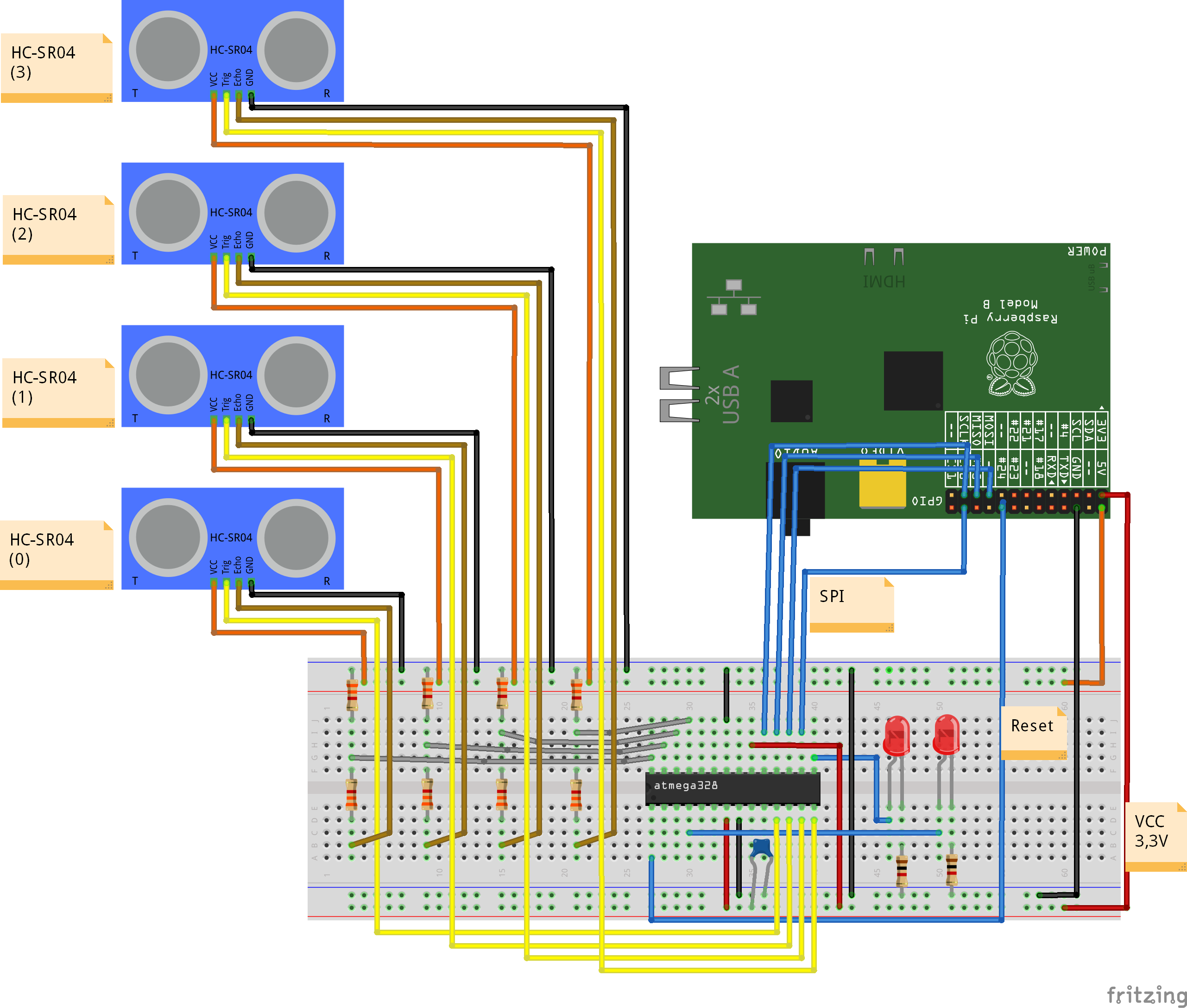
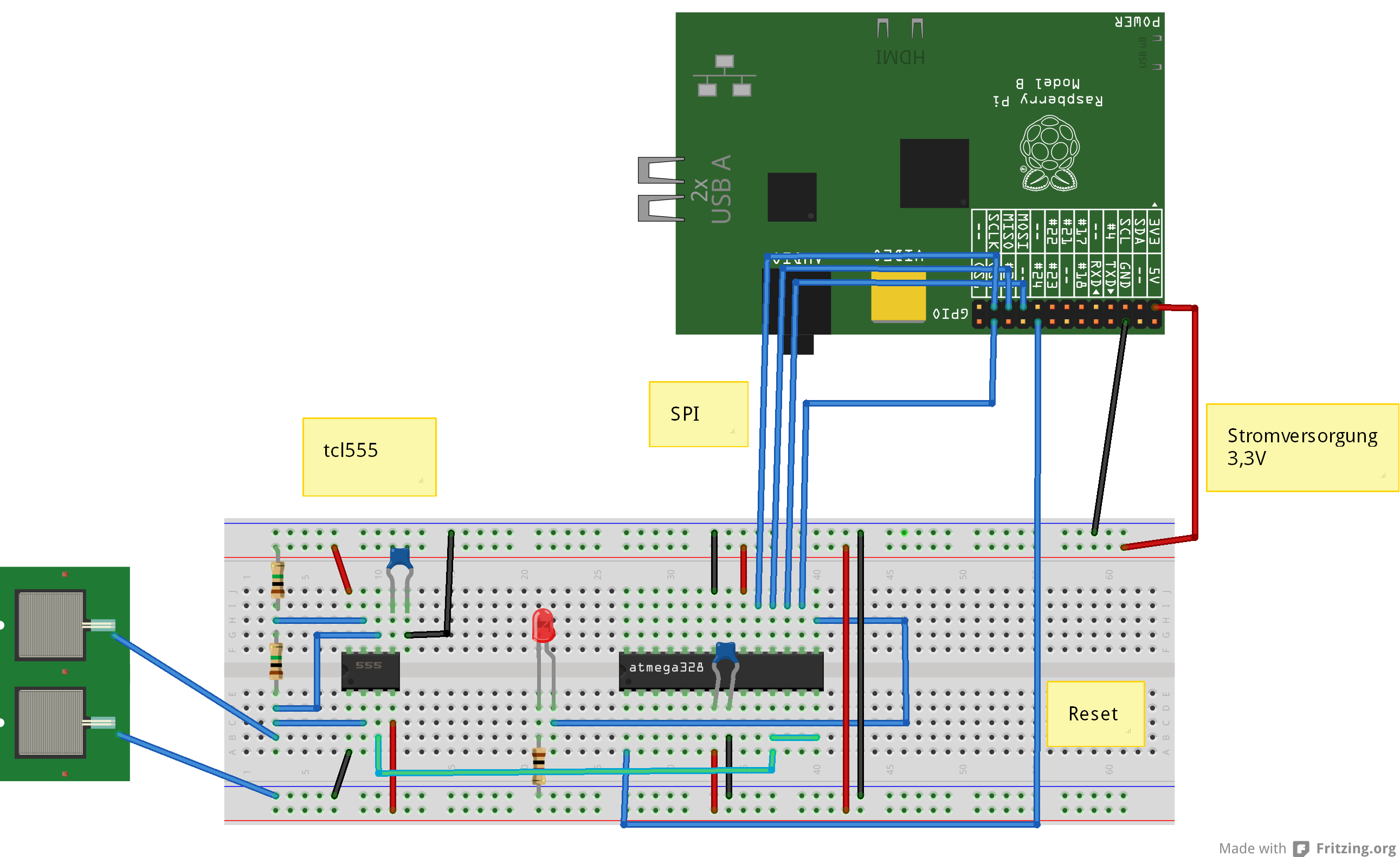
Elektrischer Aufbau

Strom des Rpi abschalten.

Prozessor auf dem Steckbrett aufbauen.

atmel_Steckplatine

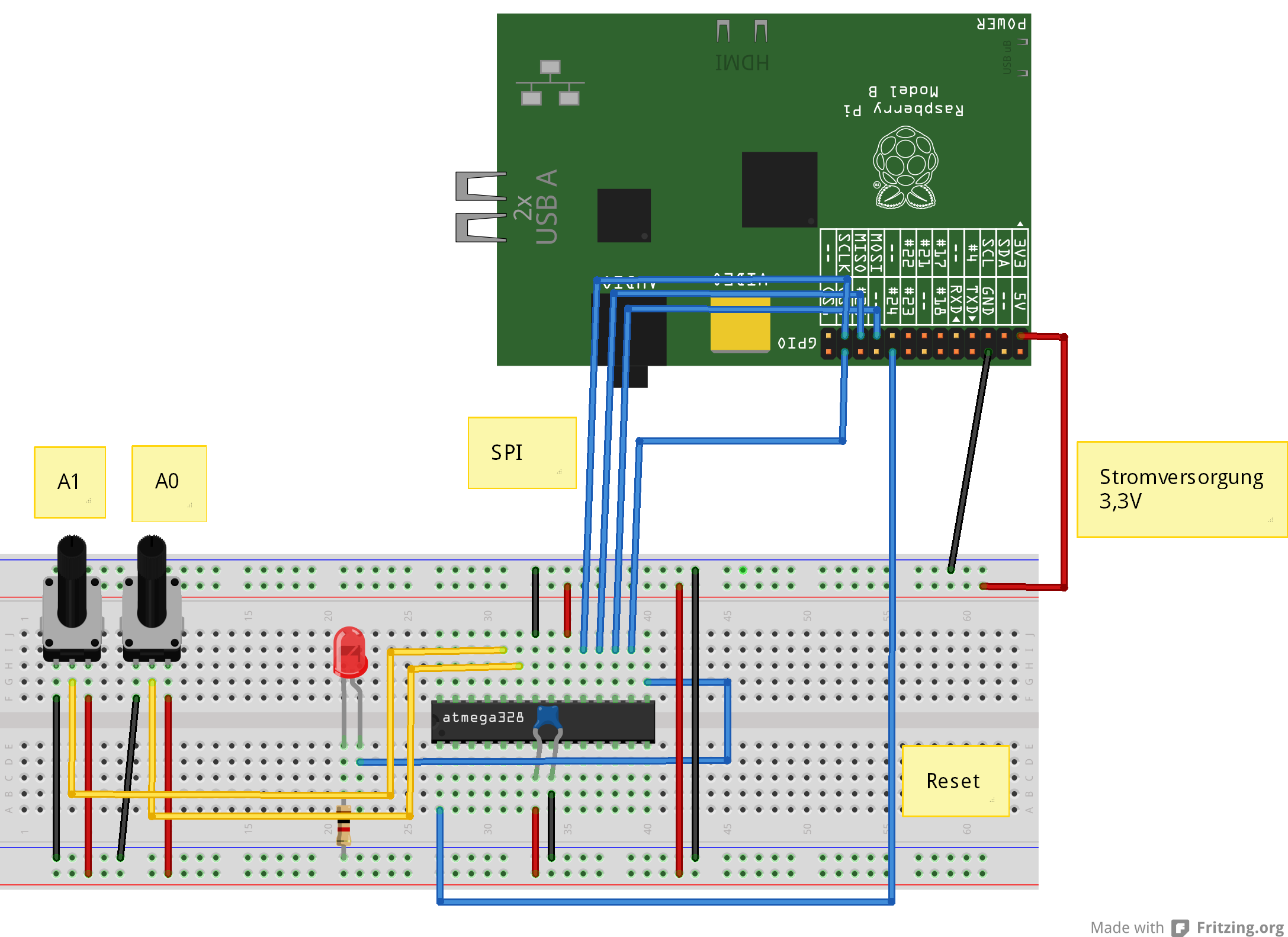
VCC des Prozessors wird aus 3.3V des Raspberry versorgt.
SPI-Verbindung MISO, MOSI, SCK und SS an CS0 des RPI.
RESET des Prozessors Pin 1 an GPIO24
LED mit Serienwiderstand 1kOhm von Port PB1, Pin 15.
ADC-Eingänge am atmega328 sind ADC0 und ADC1, Pin 23, 24.

Prozessor im Sockel

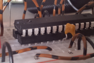
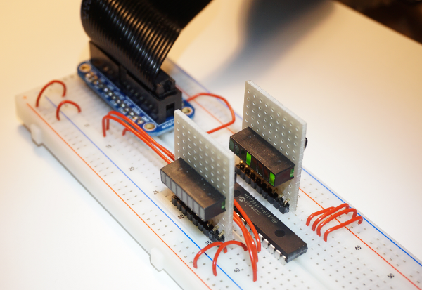
So sieht der Controller im Sockel auf dem Steckbrett aus.


Programmiersoftware auf dem Rpi installieren

sudo apt-get update
sudo apt-get upgrade -y
sudo apt-get install python-dev pip
sudo pip install spidev intelhex

Den SPI-Treiber aktivieren. Der ist über raspi-config zu starten, (enable SPI).
Oder über
sudo modprobe spi_bcm2708

Programmiersoftware in /home/pi kopieren

Das Archiv laden und auf dem RPi in /home/pi speichern und auspacken.

tar xzvf program_328.tar.gz

Überprüfen der Hardware und der Programme

Die folgenden Schritte prüfen, ob die Verkabelung korrekt ist und die Programmierung des Controllers möglich ist.

Fuses auslesen

cd ~/program_328
sudo python src/program.py -rf

Die Ausgabe sollte folgendermassen aussehen

PROGRAMMING_READ_CALIBRATION_BYTE b0 10110000
 PROGRAMMING_READ_EXTENDED_FUSE_BITS ff 11111111
 BODLEVEL0 1
 BODLEVEL1 1
 BODLEVEL2 1
 PROGRAMMING_READ_FUSE_BITS e2 11100010
 CKSEL0 0 ENABLED
 CKSEL1 1
 CKSEL2 0 ENABLED
 CKSEL3 0 ENABLED
 SUT0 0 ENABLED
 SUT1 1
 CKOUT 1
 CKDIV8 0
 PROGRAMMING_READ_FUSE_HIGH_BITS d9 11011001
 BOOTRST 1
 BOOTSZ0 0 ENABLED
 BOOTSZ1 0 ENABLED
 EESAVE 1
 WDTON 1
 SPIEN 0 ENABLED
 DWEN 1
 RSTDISBL 1
 PROGRAMMING_READ_LOCK_BITS ff 11111111

Wenn es Fehlermeldungen gibt (Device not in sync), dann liegt ggf ein Schaltfehler vor oder der Prozessor ist bereits mit unpassenden Fuses programmiert.
Dann erst mal nicht weitermachen und Verkabelung überprüfen. Wenn diese stimmt, dann externen Takt anschliessen.

Aktuelles Programm auslesen

Wenn die Ausgabe stimmt, dann kann man versuchen das aktuelle Programm auszulesen. Das ist bei einem neuen Prozessor noch leer. Hier dient das zu einer weiteren Überprüfung der Kommunikation.

cd ~/program_328
sudo python src/program.py -r

Die Ausgabe sollte wie folgt aussehen

python src/program.py -r
 ('read', 'out.hex')
 programming_readCode
 programming_enable
 ('PROGRAMMING_ENABLE', [172, 83, 0, 0])
 (0, [255, 255, 83, 0])
 programming_enable end
 programming_disable
 programming_readCode ende
 ok

Test-Programm in den Controller laden

Sind die bisherigen Schritte erfolgreich, dann kann man das erste Testprogramm in den Prozessor laden. Es sollte die LED blinken lassen.

cd ~/program_328
sudo python src/program.py -p 328/steckbrett_328_blink.hex

Jetzt sollte die LED langsam blinken.

Fuses für Oszillator programmieren

Der Microcontroller läuft bisher mit dem internen Oszilator, aber durch einen Teiler wird die Frequenz auf 1MHz heruntergesetzt. Der Teiler kann mit den Fuses abgeschaltet werden und der Controller läuft dann mit 8MHz, was bei 3.3V Betriebsspannung das Maximum ist für diesen Controller.

Die Fuses nur programmieren, wenn es bei den vorherigen Schritten keine Fehler gab und die LED auch blinkt.

cd ~/program_328
sudo python src/program.py -wf

Das Blinken hört kurz auf, und sollte dann deutlich schneller wieder anfangen, 5 mal die Sekunde.
Jetzt der Oszillator konfiguriert  und der Controller läuft mit 8MHz.

Anwendungsprogramm in den Controller laden

Jetzt kann das eigentliche Anwendungsprogramm geladen werden. Es sorgt für regelmässiges Auslesen der AD-Werte ADC0, ADC1.
cd ~/program_328
sudo python src/program.py -p 328/steckbrett_328.hex

Nach dem Programmieren oder Einschalten des RPI mit dem Steckbrett sollte die LED 5 mal leuchten.

Anwendungsprogramm – Testprogramme

Die LED blinken lassen, lange hell und kurz dunkel.
cd ~/program_328
sudo python src/test_blink.py

Auslesen der Version des 328-Programms
cd ~/program_328
sudo python src/test_get_version.py

Die Anzeige sollte ’93 09′ sein; die zweite Zahl kann höher sein.

Auslesen der adc_0-Werte
cd ~/program_328
sudo python src/test_adc_0.py

Scratch-Verbindung

Wenn die Tests für die Anwendungssoftware funktionieren, kann die Verbindung mit Scratch in Betrieb genommen werden.

cd ~/scratchClient
sudo python src/scratchClient.py -config config/config_adc_atmel328.xml

Die Konfiguration kann über Parameter angepasst werden und erlaubt das An-Abschalten der AD-Kanäle. Die Referenzspannung kann 3.3-V sein oder die interne 1.1V-Referenz.
Die 1.1V-Referenz kann z.B. mit einem Temperatursensor TMP036 benutzt werden.

Die 3.3V-Referenz ist ideal, wenn Potentiometer ausgelesen werden.

Die Werte der AD-Wandler werden als ‘adc_0’ und ‘adc_1’ an Scratch geschickt, Wertebereich 0..1023.
Befehle von Scratch an den Controller sind ‘led_off’, ‘led_on’.

SPI-Kommunikation zwischen RPi und Controller

Der Controller muss alle Befehle, die vom RPi gesendet werden überprüfen und die entsprechende Aktion ausführen. Der Controller muss das so schnell erledigen, dass die nächste Anfrage des RPi schon die korrekten Daten erhalten kann.

Die Übertragungsrate kann deshalb nur relativ langsam sein mit 240kHz. Das ist aber bei der Kommunikation mit Scratch kein Problem.

Trotz dieser Beschränkungen wurde SPI gewählt, da diese Verbindungen bereits zum Programmieren des Controllers vorhanden sind.

Anhang: GPIO#4 des RPi als Taktgenerator für den 328

Der GPIO#4-Pin kann als Taktausgang konfiguriert werden. Das dafür notwendige Programm ist im bin/-Verzeichnis enthalten, Es basiert auf Code von guzunty.org.

GPIO#4 mit den XCLK-Eingang des Controllers verbinden.  Dann das Programm bin/gz_clock_1.92MHz starten.

cd bin
chmod +x gz_clock_1.92MHz 
sudo ./gz_clock_1.92MHz

Die Ausgabefrequenz ist ca 2MHz.

Während das Programm läuft, das Auslesen und Schreiben der Fuses ausführen.
Dann diese Verbindung wieder trennen.

Update history:
2014-04-01 Fixed connections of LED