The 23S17 is the chip used on piFace, It can be used also on a breadboard, providing 16 extra IO-pins for the raspberry.
The adapter adapter.mcp23s17.MCP23S17_Adapter expands the IO-capabilities by 16 ports, either input or output.
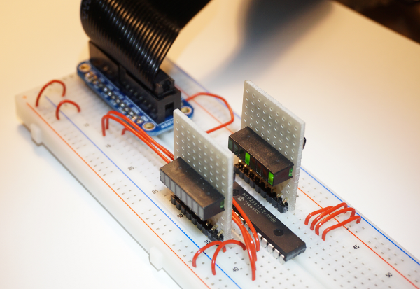
On the image you see the breadboard setup with the device 23s17, connected with an adafruit breadboard adapter to raspberry pi. The small boards plugged in vertically contain 8 LED with a resistor array. I use those whenever I need more than one LED on a setup.
Programming details
This adapter was a challenge. It needed a configuration specific for each adapter instance of this type, and this complexity was beyond the available <parameter/>-tags. The decision was to break the configuration phase into multiple steps, where after basic creation and setup of the adapter instance the configuration manager passes control to the adapter and provides the local xml config node in this call. The adapter reads the <io/>-tags, configures the necessary adapter methods for sending and receiving variables and gets the device settings for input, output direction and pullup setup.
Configuration details
The device 23s17 allows to have up to 8 devices ‘in parallel’ on one SPI chip select. These devices have hardwired distinct slave addresses. In the configuration, this slave address must be given.
        <parameter name='spi.bus' value='0' />
        <parameter name='spi.device' value='0' />
        <!-- slave address must match the hard wired slave address on the device -->
        <parameter name='23s17.addr' value='0' />
The IO direction for the port pins is defined by <io/>-tags.
        <io id='GPA0' dir='out' />
        <io id='GPA1' dir='out' />
        <io id='GPA2' dir='out' />
        <io id='GPA3' dir='out' />

        <io id='GPA4' dir='out' />
        <io id='GPA5' dir='out' />
        <io id='GPA6' dir='out' />
        <io id='GPA7' dir='out' />

        <io id='GPB0' dir='in' pullup='none'/>
        <io id='GPB1' dir='in' pullup='none'/>
        <io id='GPB2' dir='in' pullup='none'/>
        <io id='GPB3' dir='in' pullup='none'/>

        <io id='GPB4' dir='in' pullup='weak'/>
        <io id='GPB5' dir='in' pullup='weak'/>
        <io id='GPB6' dir='in' pullup='weak'/>
        <io id='GPB7' dir='in' pullup='weak'/>
It is generally a good idea to define all of the port pins. Technically it is needed to define those which are used in the application. The id-values are predefined and must be used as seen here.
For ports defined as dir=’out’ outputs, the corresponding adapter input methods can be used:
        <input_value name='inputGPA4'>
            <!-- variable name is the name of the scratch variable which is
                 send out to the adapter -->
            <variable name='input_4'/>
        </input_value>
For ports defined as dir=’in’ inputs, the corresponding adapter output methods can be used:
        <output_value name='outputGPB2'>
            <sensor name='output_2'/>
        </output_value>
The variables send out from scratch are ‘0’, ‘1’ to set the output pin of the 23s17 to low, high.
The sensor values received from scratch are ‘0’, ‘1’ for the input pin of the 23s17 receiving low, high.