Parts list
- 1 breadboard
- 3 LED, green, yellow, red. datasheet
-
3 resistors, 150 Ohm
- 1 button
- 6 Flexjumper m/f
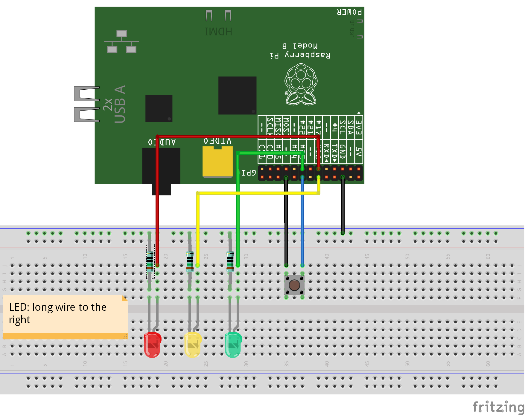
The LED has one pin longer than the other. This connector is the anode ("positive-side"). This pin is marked in the sketch.

circuit diagram
GPIO17: red LED
GPIO18: yellow LED
GPIO22: green LED
GPIO23: button (internal pullup needed)
|
To get a larger image, rightclick on image and select 'open image in new tab'. |