Author Archives: ghp_Ar7p

Raspberry Pi GPIO to web page

In the Rasperry Pi forum, there are quite often questions on how to get a GPIO pin status displayed on a web page.

Common attempts are with CGI scripts; webiopi or other frameworks are proposed. CGI is quite outdated; and complex frameworks handle many technologies under the hood and leave few opportunities to learn.

I usually propose an architecture based on a python web application server, using websockets to send events to the browser. The browser uses javascript to display the data. Collection of GPIO events is done in a thread and data are sent through a queue to the python web application server. This architecture can be tested step by step and can be adjusted to different needs.

An overall sketch of the modules shows the connection between the components.

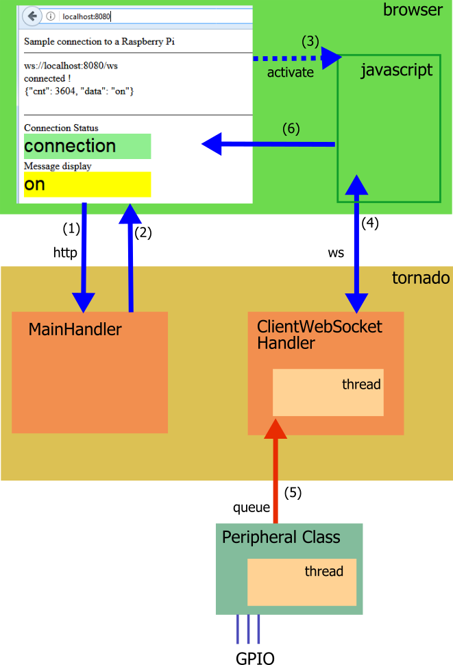
Basic sequence is: (1) Browser requests web page from server, (2) server provides web page and (3) javascript in browser is activated. (4) Javascript opens a websocket to the server. In the server, there are handler for the http request and web socket. The peripheral access is handled in a separate class and (5) sends data through a queue to the web socket handler. (6) in browser, javascript sets the received data into the html-document.

(1) Browser requests web page. The python web application server is responsible to handle this.

(2) To provide the page, the ‘tornado’ package is used. All these web app servers consist of Handler classes for various purpose. The tornado  framework uses a mapping from web request pathes to the Handlers.

def make_app():
    return tornado.web.Application(
                 [
                     (r"/"  , MainHandler),
                     (r"/ws", ClientWebSocketHandler),
                 ]
                )

The ‘root’ path for a web page is ‘/’. This is the  path a browser requests when http://heppg.de is requested. The http requests have various types, the usual request for a page is a ‘get’ request. The tornado routes this request to the MainHandler, and as it is a get request the method called is the ‘get()’-method.

To tell the whole story, the app server is initialized with

if __name__ == "__main__":
    print("start")
    app = make_app()
    app.listen(8080)
    try:
        tornado.ioloop.IOLoop.current().start()
    except KeyboardInterrupt:
        peripheral.stop()
        runMessageSend = False
        tornado.ioloop.IOLoop.current().stop()
    print("stopped")

In this code, there is also the port 8080 in the listen-statement. The url for a browser is

http://localhost:8080

or

http://127.0.0.1:8080

There is extensive documentation on the tornado web site ‘.tornadoweb’.

A basic implementation for the MainHandler is

class MainHandler(tornado.web.RequestHandler):
    def get(self):
        self.write( "hello world" )

Instead of the simple ‘hello world’ a web page is produced. Html pages are xml structures, containing <head> and <body>-Elements.

class MainHandler(tornado.web.RequestHandler):
    def get(self):
        self.write( """<html>
    <head>
        <title>Websocket sample</title>
    </head>
    <body>
        Sample connection to a Raspberry Pi
    </body>
</html>"""

The quotation with the three quotes allows to use multiline content, which makes editing simpler.

So far the page contains only the basic elements. As we later need some boxes to add text, these are defined with labels.

"""<html>
    <head>
        <title>Websocket sample</title>
    </head>
    <body>
        Sample connection to a Raspberry Pi
        <hr/>
        <div>
           <div  style="position:relative; width:400px; height:80px;" >
               <div id="addr" style="width:400px; height:20px;">    addr    </div>
               <div id="status" style="width:400px; height:20px;">  status  </div>
               <div id="msg" style="width:400px; height:20px;">     message </div>
           </div>
        </div>

        <hr/>

        Connection Status
        <div id="connection" style="position:relative; width:200px; height:40px;background:lightgrey; font: 30px arial, sans-serif;" >
            connection
        </div>
        Message display
        <div id="feld" style="position:relative; width:200px; height:40px;background:lightgrey; font: 30px arial, sans-serif;" >
            message
        </div> ..."""

(3) The javascript part plays its role now. With javascript, websockets can be opened and data can be send to the server or received from the server.

(4) To open a socket, the address needs to be build from the servers address. As the web page is received from the server, this is already known inside the browser context. Instead of http:// as the protocol, the protocol used is ws://. For a local connection, this results in “ws://localhost:8080/ws”. The trailing “/ws” is needed for the tornado routing which addresses this request to the WebSocketHandler.

var addr = "ws://" + window.location.hostname + ":" + window.location.port + "/ws";
var websocket = new WebSocket( addr );

Javascript uses ‘callback’ methods on websocket events.

    websocket.onmessage = function(e){
        ...
    }
   
    websocket.onopen = function(){
       console.log('Connection open!');
       ...
    }
   
    websocket.onclose = function(){
       console.log('Connection closed');
       ...
    }

The content is abbreviated … for clarity. The console.log(‘hello’); is a convenient way to debug javascript in a browser. If firefox is used, the debugger is available inside the browser. In earlier releases there was usually ‘firebug’ used, an extension to firefox. In newer releases – here I use 53.3 – firebug is no longer supported and “Firefox DevTools” instead. These are activated with a right click in the page and ‘inspect element’.

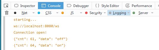
Really useful for finding out what the system is doing. Of course the debugger is also sometimes needed.

When the connection is opened, the callback function sets the status color.

    websocket.onopen = function(){
       console.log('Connection open!');
       document.getElementById("connection").style.background = 'lightgreen';
       document.getElementById("status").innerHTML = 'connected !';
    }

The elements retrieved from the html document are the named ‘div’ sections ‘connection’ and ‘status’.

Next important step is inside the python app server. When socket is opened, an instance of ClientWebSocketHandler is created. In the current application, the class starts a thread which shuffles data from a queue into the send method. So whenever a message is on the queue, this message is sent to the browser.

# a variable to gracefully stop the threadsrunMessageSend = True       

class ClientWebSocketHandler(tornado.websocket.WebSocketHandler):
    def __init__(self, args, kwargs):
        tornado.websocket.WebSocketHandler.__init__(self, args, kwargs)
        print("ClientWebSocketHandler.init")
       
        self.my_thread = threading.Thread(target = self.run)
        self.my_thread.start()
       
    def run(self):
        while runMessageSend:
            try:
                # something on the queue ?
                s = sendQueue.get(block=True, timeout=0.1)
            except Exception:
                continue 
            # doublecheck if connection available
            if self.ws_connection is None:
                print("discard ", s) 
            else:
                print("send ", s) 
                try:
                    # and send toward the browser
                    self.write_message(s )
                except Exception:
                    pass

(5) The other side of the queue can be used as needed. As a sample, here just a debug-Sending class which sends ‘on’, ‘off’ packed in a json telegram.

# messages from Periphaeral Class to Websocket
sendQueue= Queue.Queue()

class PeripheralDebug:
    """Debug class"""
    def __init__(self, sendQueue):
        self.sendQueue = sendQueue
       
    def start(self):
        self.runit = True
        blinkThread = threading.Thread(target=self.blink)
        blinkThread.start()
 
    def stop(self):
        self.runit = False
               
    def blink(self):
        cnt = 0
        while self.runit:
            self.sendQueue.put( { 'data': 'on', 'cnt' : cnt } )
            cnt += 1
            time.sleep(0.5)
            self.sendQueue.put( { 'data': 'off', 'cnt' : cnt } )
            cnt += 1
            time.sleep(0.5)

The json telegrams “{ ‘data’: ‘on’, ‘cnt’ : cnt }” contain the ‘data’-element and a counter ‘cnt’. It is usually a good idea to pack a telegram counter into a telegram. This helps to find out whether messages are lost or a connection was broken for some time.

The queue is created with Queue.Queue(), which is typical for python 2; in python3 it is more consistent with queue.Queue().

The PeripheralDebug-Class is started with

peripheral = PeripheralDebug()
peripheral.start()

Instead of this debug-Class, a ‘real’ PeripheralGPIO class can be used. When the Telegram is the same, and the queue is same queue as before, this can be exchanged easily.

class PeripheralGPIO:
    """Connection to a GPIO pin"""
    def __init__(self, sendQueue):
        self.sendQueue = sendQueue
       
        GPIO.setmode(GPIO.BCM)
        GPIO.setwarnings(False)
       
        self.channel = 4
        GPIO.setup(self.channel, GPIO.IN, pull_up_down=GPIO.PUD_UP)

    def start(self):
        self.runit = True
        blinkThread = threading.Thread(target=self.run)
        blinkThread.start()

    def stop(self):
        self.runit = False
       
    def run(self):
        cnt = 0
        prev = None
        while self.runit:
            res =  GPIO.input(self.channel)
            if prev != res:
                if res:
                    self.sendQueue.put( { 'data': 'on', 'cnt' : cnt } )
                else:
                    self.sendQueue.put( { 'data': 'off', 'cnt' : cnt } )
                cnt += 1
                prev = res
            # for debouncing and limiting number of events per time
            time.sleep(0.01)

In IT terminology, these two classes PeripheralGPIO and PeripheralDebug use the same interface. Unfortunately,  in python Interfaces are not very prominent. To make this ‘Factory Pattern’ complete, there is also a PeripheralFactory which returns either the debug-version or the GPIO-version of these classes.

class PeripheralFactory:
    @staticmethod
    def getPeripheral(debug):
        if debug:
            return PeripheralDebug(sendQueue)
        else:
            return PeripheralGPIO(sendQueue)
                   
peripheral = PeripheralFactory.getPeripheral(debug)
peripheral.start()

(6) Last step is to display the data from the websocket in the browser, so javascript gets this task:

    websocket.onmessage = function(e){
        var server_message = e.data;
        var obj = JSON.parse(server_message);
       
        document.getElementById("feld").innerHTML = obj.data;
        if ( obj.data == "on" )
        {
            document.getElementById("feld").style.background = 'yellow';
        }
        else
        {
            document.getElementById("feld").style.background = 'lightblue';
        }
        console.log(server_message);
        document.getElementById("msg").innerHTML = server_message;
    }

The message data are retrieved from the event-attribute data “e.data”. As this message is  json, this is parsed with JSON.parse(server_message); returning an object. The data part of the json dictionary is retrieved with obj.data and accordingly the status box is getting its color.

The complete code can be downloaded here.


Sonic Pi controlled from scratch

Sonic Pi is great software to produce sounds and to program melodies.

Sonic Pi has an API which allows to use some of the program statements from an external program. There are some places in the web where this feature is used with erlang- or ruby-code.

This adapter for scratchClient and the programming in scratch  is not intended to be a replacement to the Sonic Pi programming language. The reason is the timing of commands in scratch, which is not very precise and command execution delays are audible. But it can be used as a high quality sound generator for scratch games.

The API uses Open Sound Control OSC-format for the messages, so the Sonic Pi commands needs to be packed into this format. This format packs strings into a byte stream with null-bytes as terminators. An example is sending ‘play 60’, which needs the basic parameters ‘/run-code agent-name code’; the agent used is SONIC_PI_CLI and the command part is here ‘play 60’.

The OSC message is as follows

b'/run-code\x00\x00\x00,ss\x00SONIC_PI_CLI\x00\x00\x00\x00play 60\x00'

The strings are zero padded to 4 byte boundaries; the type of option is given by the two string-types ‘s’ after the command.

This conversion is done with the python_osc library; this library needs to be installed in addition to the standard install procedure.

sudo pip3 install python_osc

This library is available for python3 only. As scratchClient is continuously moving towards python3, this is not a restriction.

The software runs on linux and windows. scratchClient and Sonic Pi need to run on same machine, as Sonic Pi accepts only local connections.

Commands are ‘play 50’ for a simple beep, or ‘use_synth :chiplead ; play 80,release: 0.08 ; sleep 0.1 ; play 83, release: 0.08’ for a sequence of notes.

sonic.gif

In scratch, just set a variable sonicpi_cmd to the command needed.
More details in the scratchClient docs in http://www.heppg.de/ikg/administration/ … lient.html

The setup requires to have Sonic Pi running on same computer as scratchClient.
The commands executed are displayed in Sonic Pi window in the protocol-pane.

Errors in commands are displayed in the Sonic Pi window, so when no sound is produced it is a good place to look.

A more advances example is ‘Alle meine Entchen’ played from a list of sounds and a second list with time delays.

The script uses two lists to produce sound. ‘ame’ is containing sonic pi commands, ‘amd’ is providing timing information.

With these two lists, the script is just iterating through the list and sending commands to sonicpi_cmd-variable. As scratch is not sending out variable information when content does not change, it is needed to reset the information to an empty string in order to get notes repeated.

The scratch 1.4 project can be downloaded here.

Have fun !

scratchClient and scroll_phat_hd

There is a nice little led matrix moard from PIMORONI, “SCROLL PHAT HD”. The form factor is for the pi zero, but it runs well also with a pi 3.

scroll_phat_hd

scratchClient offers support for this board.

The interface allows to set pixel with brightness, write large and somewhat smaller text and of course clear the display.

There is a sample scratch script in scratch/scrollphathd/scroll_phat_hd.sb

There are quite a few commands from scratch which need parameters.
This is not a trivial task with scratch. Here a variable is used as a ‘command’-Variable ‘sph_command which receives operation names optionally with parameters.


Clear the display. There is also a broadcast command for this ‘clearDisplay’


Set a pixel at x=1, y=1, brightness = 1.0. Valid ranges are x in [0..16], y in [0..6], brightness is [0.0..1.0]. Values out of scope are ignored.


Draw a box between two pixels, here between [0;0] and [17;7] with brightness 0.3. This command effectively sets all led to on.

There are two text variables provided with a 5*7-font and a 3*5 font. Not all chars are supported. The 5*7 font basically supports ascii, the 3*5 font supports digits and some extra chars as ,;.:-_+\/.
The fonts are defined in ‘pseudographics’ in a python file and can easily be expanded.

There is a sample config file available, start scratchClient with

cd ~/scratchClient
python src/scratchClient.py -c config_scrollphathd

The adapter code has been written based on code from pimoroni.

minecraft and scratchClient

On raspberry pi, there is a local minecraft release available which supports a python API.

There is a MinecraftAdapter available for scratchClient which supports this API and allows to do basic operations.

For most of the operations, there are coordinate values to be set first before the operation is performed.

Example: set position of ‘person’.

Example: set Block

There is a sample scratch application in scratch/minecraft/minecraft.sb which demonstrates the basic concepts.

There are some demo scripts in minecraft.sb. One of these writes ‘scratch’ to the landscape. There is no ‘printString’-Function in the adapter. The pixel are defined in a local list, containing x and y-values of pixels. The data for this array are generated by a small python script and then imported into the list.

The python code is in scratch/minecraft/scratch_x_y.py. Run it by

python scratch_x_y.py > scratch_x_y.txt

and import the txt-file into the array.

The python code is quite simple.

f0="                         *          *        "    
f1="                         *          *        "
f2=" ***   ***  * **   ***  ***    ***  * **     "
f3="*     *   * **  *     *  *    *     **  *    "
f4=" ***  *     *      ****  *    *     *   *    "
f5="    * *   * *     *   *  *  * *   * *   *    "
f6="****   ***  *      ****   **   ***  *   *    "

def printPixel(f, level):
    for i in range(len(f)):
        if '*' == f[i]:
            print(i)      # print x-koordinate
            print(level)  # print y-koordinate
            
printPixel(f6, 1)
printPixel(f5, 2)
printPixel(f4, 3)
printPixel(f3, 4)
printPixel(f2, 5)
printPixel(f1, 6)
printPixel(f0, 7)

The pixels are defined in ‘pseudographic’. It is simple to add more text, decorations or extend the output by colors ( * ==> green, # ==> red) and adjust the scratch script to take each third line for the color information.
But keep in mind that ‘the world’ is limited size for minecraft for py and coordinates should be kept in range.

scratchClient with MQTT-Adapter

MQTT Description

MQTT, Message Queue Telemetry Transport, is a is an ISO standard for a publish-subscribe based messaging protocol. It is based on TCP/IP (the ‘usual’ network protocol) and especially designed for small devices and low network bandwidth.

A typical infrastructure contains at least one MQTT-Broker and one to many clients connected to the broker. This infrastructure can be spread to many computers.
A broker just receives messages sent by clients and distributes these to those clients which have subscribed to messages with specific topics.

A MQTT-message is build of a topic and a payload. Topics are strings like ‘home/room1/temperature’ or ‘client1/status’. Payload can be whatever data are needed to be send, this can be strings, binary data as integers, data structures. The broker does not process the data, it is up to the subscriber to ‘know’ how to process the payload.

From the description so far it is clear that there is the need to design the topics in a way that the system is extensible. This is paperwork, most of the time.

There are many more features in MQTT. See the mqtt.org homepage for more details.

scratchClient MQTT-adapter configuration

For scratchClient, the MQTT-adapter can publish messages and subscribe to topics. The topics managed are defined in the config xml. a sample file is included in the distribution.

    <adapter class='adapter.iotAdapter.MQTT_Adapter'  name='mqtt'>
        <description>interface to a mqtt-server</description>
        
        <!--  
           this adapter does implicit input_value and output_value-configuration 
           based on the content of mqtt-Tag.
              mgtt/publish/@variable definitions are used as scratch variable names.
              mgtt/subscribe/@variable definitions are used as scratch sensor names.
        -->
        <extension>
        <mqtt>
            <!--  when @variable is omitted, the topic is taken as variable name -->
            <publish topic="scratch/sample/a_value" />
            <publish topic="scratch/sample/b_value" variable="b_value" />
            <publish topic="scratch/sample/c_value" variable="c_value" />
        
            <subscribe topic="scratch/sample/d_value" variable="d_value" />
        </mqtt>
        </extension>
        
        <parameter name="mqtt.server" value="192.168.2.133"  />
        <parameter name="mqtt.port" value="1883"  />
    </adapter>

ScratchClient needs definitions on which variables to send out ‘publish’ and which ones to provide as sensor values ‘subscribe’.

The publish definition can be as short as the example here. This short definition takes the topic name also for the scratch variable name.

<publish topic="scratch/sample/a_value" />

In scratch, a variable named ‘scratch/sample/a_value’ will be published by the topic ‘scratch/sample/a_value’.

When more control on the scratch variable name is needed, the extended definition can be used:

<publish topic="scratch/sample/b_value" variable="b_value" />

Now a variable in scratch ‘b_value’ is published with topic ‘scratch/sample/b_value’.  I prefer to take the scratch name as the last section in the topic, but the variable name can be any valid name for scratch, e.g. ‘temperature’ or ‘xyz’.

<publish topic="scratch/sample/b_value" variable="temperature" />

For the subscribers, the definition is

<subscribe topic="scratch/sample/d_value"  />

This will result in a sensor value reported with name ‘scratch/sample/d_value’. There is also the possibility to match the sensor name by using the extended form

<subscribe topic="scratch/sample/d_value" variable="temperatureOfSample" />

Please note that wildcards in topics should not be used.

The parameters for the adapter define the connection details

        <parameter name="mqtt.server" value="192.168.2.133"  />
        <parameter name="mqtt.port" value="1883"  />

For the sample, the plain IP-address is given. Use ‘localhost’ or ‘127.0.0.1’ when the mqtt-broker is on same machine.

The MQTT-Adapter is based on eclipse-paho python library and is available on raspberry pi, linux, windows and many more platforms.

For the broker there is mosquitto available for raspberry pi. Just install by

sudo apt-get install mosquitto

This installs the server and starts the server in the background. This is good for a private environment. For a public installation, be sure to look into the docs for securing the environment.

Sample setup

In the scratchClient distribution, there is a sample configuration for a small usage scenario. This requires two computers, as scratch 1.4 with scratchClient can’t be started multiple times on one machine. The sample transmits a button press from GPIO and publishes by a topic ‘scratch/sample/button’ to the second installation, where in scratch a popup is triggered.

The config files are for computer 1 scratch/mqtt/dev_0/device_0.xml
the config files are for computer 1 scratch/mqtt/dev_1/device_1.xml

Be sure to edit the files to have the correct IP-addresses for the mqtt-broker.

On computer ‘dev_0’, there is a button needed from from GPIO17 (BCM) to GND.

   <adapter class='adapter.iotAdapter.MQTT_Adapter'  name='mqtt'>
        <description>interface to a mqtt-server</description>
        <extension>
        <mqtt>
            <publish topic="scratch/sample/button" variable="button" />
        </mqtt>
        </extension>
        
        <parameter name="mqtt.server" value="192.168.2.160"  />
        <parameter name="mqtt.port" value="1883"  />
    </adapter>
    <!-- =========================================================================== -->
    <adapter class='adapter.gpio.GpioEventInput' name='button_s0'>
        <gpio port='GPIO17'>
            <default dir='IN' pull='PUD_UP'  />
            <active dir='IN' pull='PUD_UP'/>
        </gpio>
        
        <output name='button_pressed'>
            <broadcast name='s0_high'/>
        </output>
        <output name='button_released'>
            <broadcast name='s0_low'/>
        </output>
        
        <parameter name='poll.interval' value='0.05' />
        <parameter name='value.inverse' value='true' />

    </adapter>

The scratch code for dev_0 is straightforward.

The adapter GpioEventInput sends events ‘s0_low’ or ‘s0_high’ on button release/ press. The parameter ‘value.inverse’ for this adapter switches high/low values. This is needed here as the button is connected from GPIO to GND and a button pressed is electrically a low signal.
The scratch code translates the button events to variable values for the MQTT-Adapter. When the button is pressed, a value ‘pressed’ is set to variable ‘button’. This variable is then sent to scratchClient where the MQTT-Adapter publishes the value with topic ‘scratch/sample/button’.

With a mqtt-client as mqtt.fx this topic can be observed. The client ‘mqtt.fx’ is a java-fx based tool which unfortunately is not easy to execute on raspberry due to missing fx-libraries. I have this tool running on a windows machine.

For the second device another computer is needed. The config file (here only a snippet) subscribes to the well known topic “scratch/sample/button” and provides the value for a sensor variable ‘button’ in scratch.

<extension>
 <mqtt>
 <subscribe topic="scratch/sample/button" variable="button" />
 </mqtt>
</extension>

The scratch code is staightforward, the value of the variable is displayed on the stage.

scratchclient is available from the download page  http://heppg.de/ikg/wordpress/?page_id=6

python timing loop accuracy

On a raspberry pi in python, it is not possible to produce accurate timings in μs range. The question is how accurate the timing is in real live.

The issue was raised by someone asking a question in raspberry pi forum on an 80Hz timing loop “the values may not always be accurate at the milliseconds level”.

To measure this, a simple timing loop was set up in python, and the timing was measured with the help of an arduino due. The arduino due runs at 84MHz and is ideal as a versatile measuring tool for this sort of problems.

Python timing loop. The loop should produce a square wave with 12.5ms or 80Hz.

import RPi.GPIO as GPIO
import time

GPIO.setmode(GPIO.BCM)
GPIO.setwarnings(False)

pin_AO = 17
GPIO.setup(pin_AO, GPIO.OUT)

dt = 0
diff = 0.0115
while True:
    drun = diff - dt
    
    t0 = time.time()
    for _ in range(0, 1000):
        GPIO.output(pin_AO, GPIO.LOW)
        time.sleep(0.001)
        GPIO.output(pin_AO, GPIO.HIGH)
        time.sleep(drun)
    t1 = time.time();
    # calculate the deviation from ideal value 12.5 ms.
    dt = (t1 - t0) / 1000 - 0.0115 - 0.001
    print(dt)

The idea is to adjust timing based on average of last 1000 pulses.

The output of the arduino due is printed to Serial and looks like (values in μs):

...
12508
12509
12509
12514
12513
12516
12513
12509
12510
12512
12510
12515
12510
12515
12514
12515
12508
12512
12508
12514
12514
...

Grouping the output values into 10 μs slots and calculating the the number of events per group yields this bar chart. There are prox 27.000 events included the chart.

12-5ms

X-axis is slot times in μs; y-axis is count of events in the slot.

The printout of the script is (shortened)

9.77396965027e-06
0.000155053138733
1.0488986969e-05
0.000154378175735
1.00150108337e-05
0.000154267787933
9.80496406555e-06
0.000156002044678
8.39877128601e-06
0.000155970096588

This demonstrates some oscillation. Values like 0.00015 and ‘something- e-05’ are repeating. The two peaks in the diagram reflect this behavior.

Summary: precise timing with loops in python is accurate only to prox 0.2 ms.

rotary encoder performance

Rotary encoders produce two waveforms, shifted by 90 degrees, which allow to decode position and direction of movements.

The two waveforms look as given in the chart. Only one direction is shown.

encoder

In raspberry pi forum, someone asked for the performance of a python program to decode these signals.

The code used to validate python program is

import RPi.GPIO as GPIO
import time

GPIO.setmode (GPIO.BCM)
GPIO.setwarnings(False)
pin_A = 22   
pin_B = 27

Encoder_Count = 0      # Encoder Count variable
   
def do_Encoder(channel):
    global Encoder_Count
    if GPIO.input(pin_B) == 1:
        Encoder_Count += 1
    else:
        Encoder_Count -= 1

GPIO.setup (pin_A, GPIO.IN, pull_up_down=GPIO.PUD_UP)         # pin input pullup
GPIO.setup (pin_B, GPIO.IN, pull_up_down=GPIO.PUD_UP)         # pin input pullup

GPIO.add_event_detect (pin_A, GPIO.FALLING, callback=do_Encoder)   # Enable interrupt

lastCount = 0
t0 = time.time()
while(1):
    t0 += 20
    time.sleep(t0 - time.time())
    print ("{e:d} diff={d:d}".format(e=Encoder_Count, d = Encoder_Count-lastCount))
    lastCount = Encoder_Count

As a driver for these signals I use an arduino DUE.

The results for the python code on a Raspberry Pi 3 are

freq       exp     measure
   10Hz    200         200
  100Hz   2000        2000
  500Hz  10000       10000  +-2
 1000Hz  20000       20000 +-25
 2000Hz  40000       40000 -40
 3000Hz  60000       60000 -660
 5000Hz 100000     -100000 +-20, but received negative values, so python too slow to get matching level

Up to 3.000 pulses, the results are quite reliable. For a 1.000RPR encoder, these are 3 rotations per second.

Usually I recommend to use an atmel328-processor as a slave processor to handle time sensitive operations. With an arduino UNO, 16MHz, the results are precise up to 15.000Hz.
There is no complete arduino needed. A bare atmel328, clocked from GPIO4, using level shifters for clock and serial line, would be a cost effective solution.
The sketch uses interrupts for the event inputs:

const byte ip2 = 2;
const byte ip3 = 3;
volatile long counter = 0;

void ip2Int() {
  byte iip2 = digitalRead(ip2);
  byte iip3 = digitalRead(ip3);
  if ( iip2 == 1 ) {
    if ( iip3 == 1 ) {
      counter --;
    }
    else
    {
      counter ++;
    }
  }
  else // ip2 == 0
  {
    if ( iip3 == 1 ) {
      counter ++;
    }
    else
    {
      counter --;
    }
  }
}

void ip3Int() {
  byte iip2 = digitalRead(ip2);
  byte iip3 = digitalRead(ip3);
  if ( iip2 == 1 ) {
    if ( iip3 == 1 ) {
      counter ++;
    }
    else
    {
      counter --;
    }
  }
  else // ip2 == 0
  {
    if ( iip3 == 1 ) {
      counter --;
    }
    else
    {
      counter ++;
    }
  }
}

void setup() {
  Serial.begin(115200);
  Serial.println("encoder");

  pinMode(ip2, INPUT);
  pinMode(ip3, INPUT);

  pinMode( 13, OUTPUT);
  pinMode(pin_sync, INPUT );
  
  attachInterrupt(digitalPinToInterrupt(ip2), ip2Int, CHANGE);
  attachInterrupt(digitalPinToInterrupt(ip3), ip3Int, CHANGE);
}

void loop() {
  long c0 = 0;
  noInterrupts();
  c0 = counter;
  interrupts();

  Serial.println(c0);
  delay(10000);
}

This code runs up to 15.000Hz, at 20.000 Hz it fails.

An obvious optimization is to change the interrupt routine and avoid the digitalRead-function for the atmel328-processor.

void ip2Int() {
  uint8_t pd = 0b00001100 & PORTD;  // pins 2,3 are PD2, PD3
  if ( pd == 0b00001000 || pd == 0b00000100 ) {
    counter ++;
  }
  else {
    counter --;
  }
}

void ip3Int() {
  uint8_t pd = 0b00001100 & PORTD;
  if ( pd == 0b00001100 || pd == 0b00000000 ) {
    counter --;
  }
  else {
    counter ++;
  }
}

This code is much faster and update rates till 50.000Hz work perfect.

With handcrafted assembler code for the interrupt-routine I would expect to extend performance even more.

Last option investigated was an arduino feather M0 board running at 48MHz.
This produces good results up to 30.000Hz, at 40.000Hz there are failures. With the results from optimized atmel328-code, there is quite a lot of optimization expected.

For the fast running signals, timing accuracy is crucial. To work around this problem, a sync pattern was used: an additional sync signal indicated start and end of measurement from generator to measurement device. Pulse sequence was 10 sec in each case.

encoder_sync

For faster signals, either optimized assembler code needs to be used, or a hardware solution with a FPGA.

Updated 2017-02-19: optimized atmel code.

scratchClient singleton reworked

scratchClient needs to run alone, as a ‘singleton’, on one computer. The reason is that concurrent access to GPIO, SPI or other resources could result in unpredictable results.

First approach was to use a pid-file with some logic. At startup, scratchClient writes its own process identification ‘pid’ into a file scratchClient.pid. When another scratchClient is started, it looks for existing pid-file, doublechecks if a process with the recorded pid is running. In this situation, the new started process stopped.

In practice, this situation arised quite often when kids started scratchClient with wrong config file and simply closed the terminal. On a fresh start in a new terminal, the ‘old’ pid file was still existing or even the previous process was still running somewhere. These situations asked too much linux knowledge from kids and teachers and often resulted in unnecessary reboots of the computers.

A better solution is that a new start of scratchClient causes previously started processes to stop. This should work inside one computer and work independent from user permissions on the process: a new scratchClient started by ‘pi’ should be able to stop a previously started process by ‘root’.

The new singleton mechanism uses a socket to achieve this behavior. On startup of scratchClient, socket 42003 is opened as a TCPServer and listens to commands.
A new started process will get errors on opening same socket as a listener, switches to client mode and issues a shutdown command to the server. Next step is then to open TCPServer on this socket.

The video shows this effect with two terminal sessions.

In upper window, scratchClient is started. Another start in lower window causes the first process to stop.

This behavior now is default for scratchClient.

The command line allows to select the singleton mechanics:

-singletonPID        when multiple instances are running, report other instance and 
                     terminate
-singletonIPC        when multiple instances are running, terminate other instance
                     used port 42003 (default from 2017-02-14)
-singletonNONE       no singleton policy applied. For debug only

Summary: new singleton mechanism introduced in scratchClient since Feb 2017.


scratch performance 2, gpioserver reaction time

Perfomance of gpioserver was examined in “gpio performance” ,

Another aspect of gpioserver performance is how fast it can react to gpio pin changes.

The measure response time, I connected an arduino due which raised gpio23 to high and measured time till raspberry responded with a high-value on gpio24.

The arduino code placed a random delay in the start of each measurement cycle in order not to synchronize with scratch. In total more than 10.000 measurements have been taken.

response

response_summaryThe x-axis are the response times. The y-axis are the number of measurements which occurred in this time slot. There is a quite uniform distribution from a few milliseconds up to 24 ms, with a few exceptions up to 40 ms. The measurements are grouped to 0.5ms slots.

Measurement taken on raspberry pi 3, scratch 2016-10-21. The arduino used is a ‘due’, 84MHt and 3.3V which is ideal to interface with raspberry.


.scratch.ini

Scratch 1.4 on raspberry pi has some possibilities to tweak the behavior.
This is done with a properties file ‘.scratch.ini’ which is usually located in /home/pi.
Note the dot in front of the file name, which makes it a hidden file for linux.
You need to enable the ‘hidden file’-feature in filemanager to see these files.

fontscale=1.2
Change the default size of fonts used for all the texts.
Values are floating point numbers, good values are [0.7 .. 1.5]

remoteconnectiondialog=0
Prevents the little sensor block dialogue to tell the using that remote sensing has been tuned on from popping up, useful for many projects
Values are [0, 1]

gpioserver = 0
Disables the gpioserver, 1 enables it, 2 makes it be on by default
Values are [0, 1, 2]
Please note that with the scratch start script, the ‘pigpiod’-code is started independent from this setting. On pi A, this takes considerable cpu power with 15-20%.

presentation= 0
Will open Scratch in presentation mode; ‘1’ will open Scratch in presentation mode
Values are [0, 1]

language=en
Some language descriptor fitting the two-letter ISO 639-1 standard
For values see https://en.wikipedia.org/wiki/List_of_ISO_639-1_codes

Values I never tested:

home = directory for home
visibledrives = a list of drive names (Windows) or root directories (Mac) to add to the file dialogues.
share = 0 or non-0. 0 means do not allow sharing of project files
proxyserver = IP for a server
proxyport = port number for the server
renderplugin = 0 or non-0. 0 will try to force not using the PAngoCairo font renderer and likely make things ugly.

Post is based on https://www.raspberrypi.org/forums/viewtopic.php?p=1031498#p1031498