Author Archives: ghp_Ar7p

gpioServer and scratchClient performance comparison for stepper driving signals

GPIO performance on raspberry pi is an often discussed topic.

New scratch uses a build in gpioServer, other options are scratchClient.
Especially stepper motors need quite high pulse rate, so I have set up a test harness for a small stepper with 2ms step width. The scenario are

  • a DMA pulse driven approach
  • a python program
  • scratch, using scratchClient
  • scratch, using GPIOserver

The main focus is on performance of scratch to GPIO.
For scratchClient, some bottleneck analysis is performed.

DMA created pulses

As expected, DMA pulse widths are precise. The glitch on third line is due to a limitation in my modified RPIO.PWM-library which does not yet allow impulse roll over. The interval time printed on the image is for four steps and precise 8ms.

dma

dma-impulse

This DMA approach is listed for reference only, as it is not easily controllable from scratch. It is either on or off, but number of pulses can’t be determined.

python created pulses

python code is also pretty good. Pulse with is exceeding the expected 8ms by 0.5ms, which could quite easily compensated by some more advanced time handling.

pythonpython

scratch and scratchClient

The scratchClient approach is expected to be slower. Time scale is changed for this chart and the result is 326ms for 4 steps, which is 40 times slower than python or DMA.

scratch_variables_scratchClient

scratchclient

scratch with gpioserver

GPIOserver, build in into scratch, is finally at 101ms, three times faster than scratch with scratchClient, only 12 times slower than python. The assymmetric pulses are due to to ‘forever loop’, I suppose.

scratch_gpioservergpioserver

All of the measurements have been taken on a RPI2, Model B, raspbian ‘jessie’, scratch is 2015-11-11.
Python is 2.7, the DMA code is a modified RPIO.PWM, adjusted for PI2.

scratchClient bottleneck analysis

The result for scratchClient was unexpectedly bad. So I have set up some tests to find out where the bottleneck is located.

scratch_broadcast_scratchClient

First approach was to change the variable based communication to the stepper module by an event based ‘broadcast’. This approach resulted in 101ms cycle time, a good match to the result from GPIOserver.

Second approach was to write a small python code which simulates scratch: a socket server for port 42001, sending out sensor updates like “sensor-update “br0.0” 0 “.

python_variables_scratchClient

python_scratchclient

The delay time was 2ms, and the result from this is a cycle time of 9ms. Pretty close to the pure python approach.
From these results it is clear that the bottleneck is on scratch side. Looks as if scratch variable access and sending them out is three times slower than sending out broadcasts from scratch.
Socket communication imposes some overhead, but is not limiting performance.

See also scratch performance 2, gpioserver reaction time

blink(1) for scratch

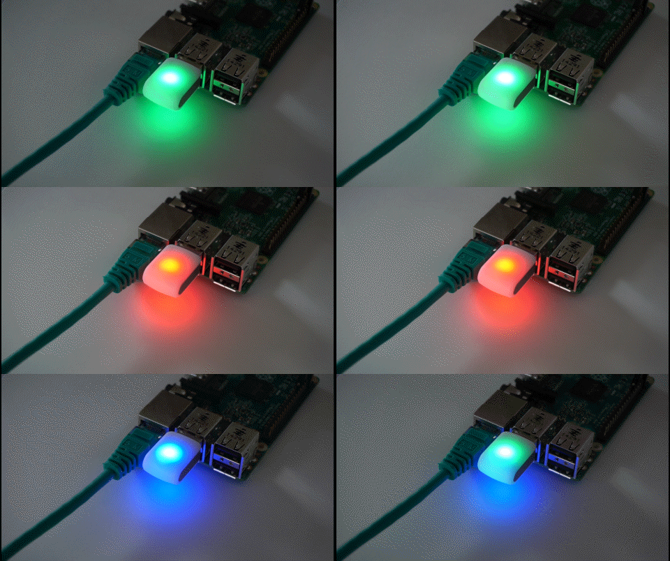
blink(1) is a neat small USB device with two RGB LED inside. See also their home page.

blink

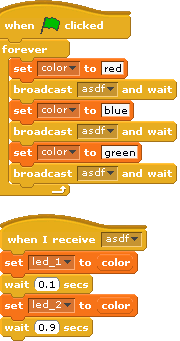
The scratch code is straightforward. With variable ‘led_1’ the LED#1 is set, and ‘led_2’ sets LED#2. The device supports also a setAll-Command, a variable ‘led_all’ or ‘led_0’ is used for this purpose.

Download and install scratchClient-Software. In addition to the usual installation of scratchClient it is needed to install ‘pyusb’. This installation is described in the documentation.

scratchClient is designed to work with raspberry pi, but as pyusb is available on linux in general, this should be generally available on these platforms.

Start scratchClient with

cd ~/scratchClient
python src/scratchClient.py -c config_blink

blink.sb

This is the sample scratch Code from the animation. The two led are controlled by a small delay.

Basically, there is the possibility to use more than one blink(1) device. These are identified by their serial number, which can be used to control them separately. Drop me a note if you need this feature.

The usb-control software needs some additional installation, see the the installation remarks in barcode scanner for details.
Making of ‘Experimentierbox’es

The workshop in school grew by a few kids, and there is the need for additional boxes. As these are no ready to buy products, there again was some design, procurement, a lot of parcels dropping in and some work in preparing plywood, electronics and cases for the PI2.

pellets

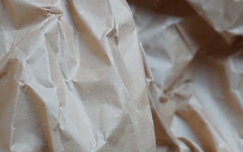
A lot of packaging material floating around.packpapier

bauteile

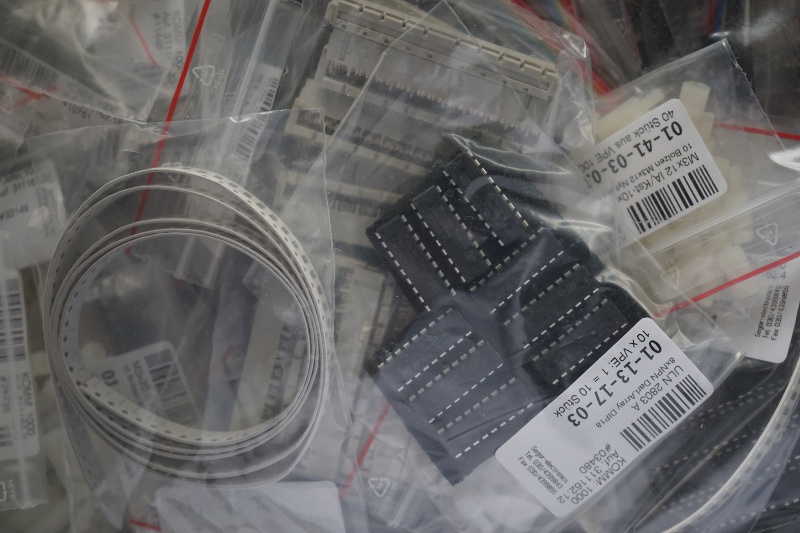
Bags full with electronic parts

design_geh

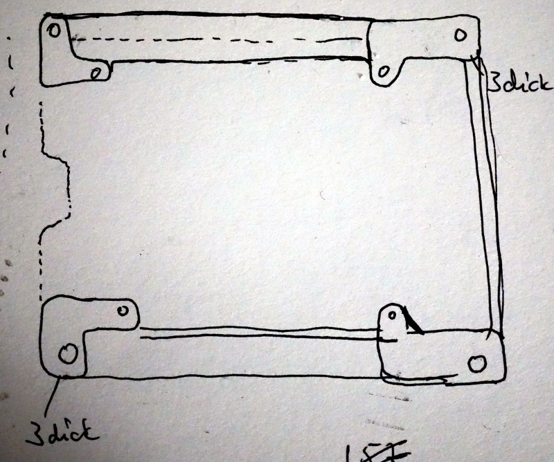
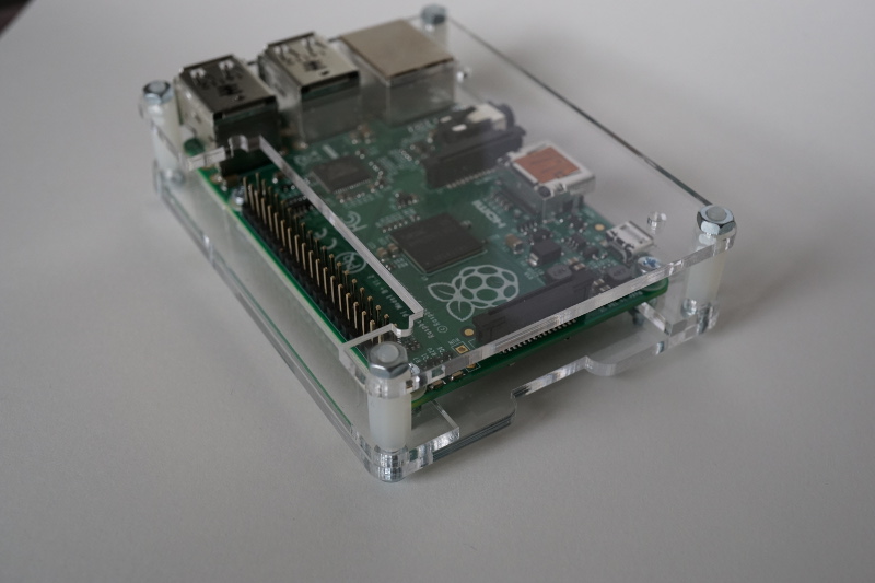
Early design sketch for the pi2 enclosure. This was needed, as the piB should be replaced. Unfortunately, it was almost impossible to get detailed  information on how the available  boxes can be mounted on a board. This was the reason to make an own design.

laserschnitt

This is how the acrylic glass arrived from the laser cutting service. There is an opaque white cover on the transparent material, a little bit burned on the edges. Nothing from this is seen when cover is peeled off.

pi2b_plexi

And the assembled encloses. Three 3mm layers, some spacers. And good looking.

multiplex_roh

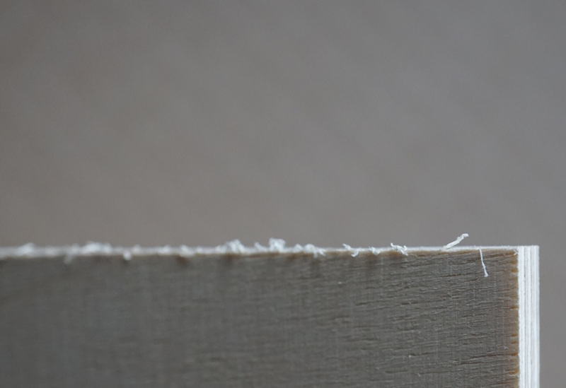
For the base board, plywood is used. The initial state after delivery of the boards clearly shows the need for sanding and some paint.

lackierung

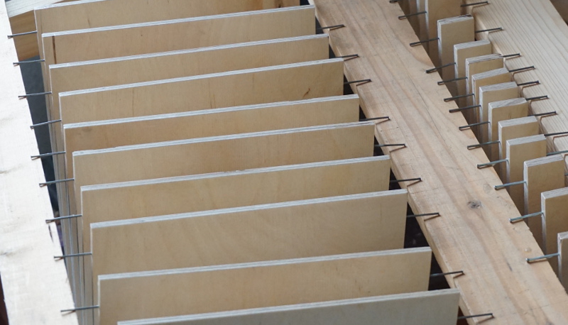
For painting, the boards got nails on both sides to be handled during drying.

schachteln

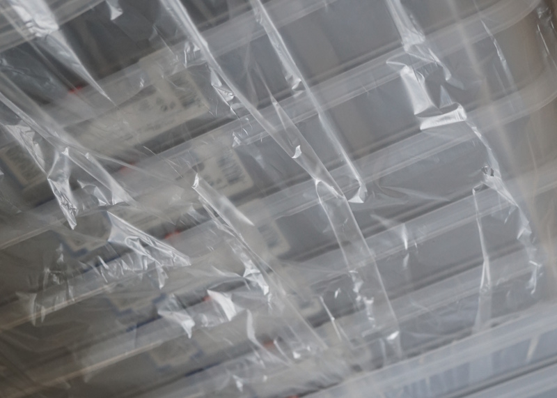
The plastic boxes where the board, pi, electronics are stored (when everything is completed).

kleine_platinen


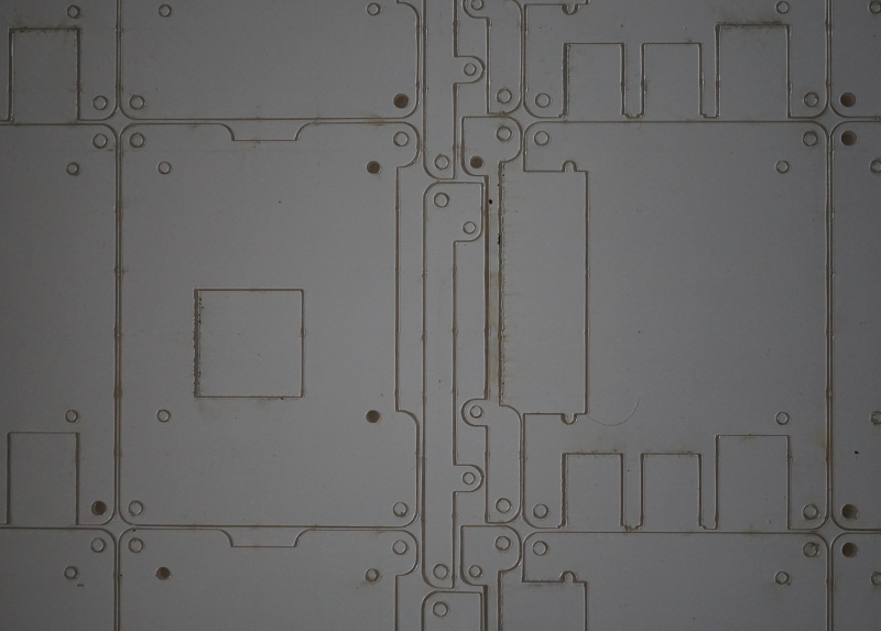
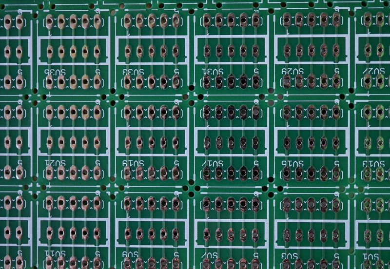
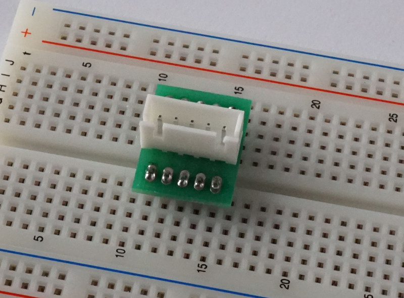
The small adapter boards are together on a larger pcb and need cutting. These are the stepper motor adapters for the breadboard.

motoradapter

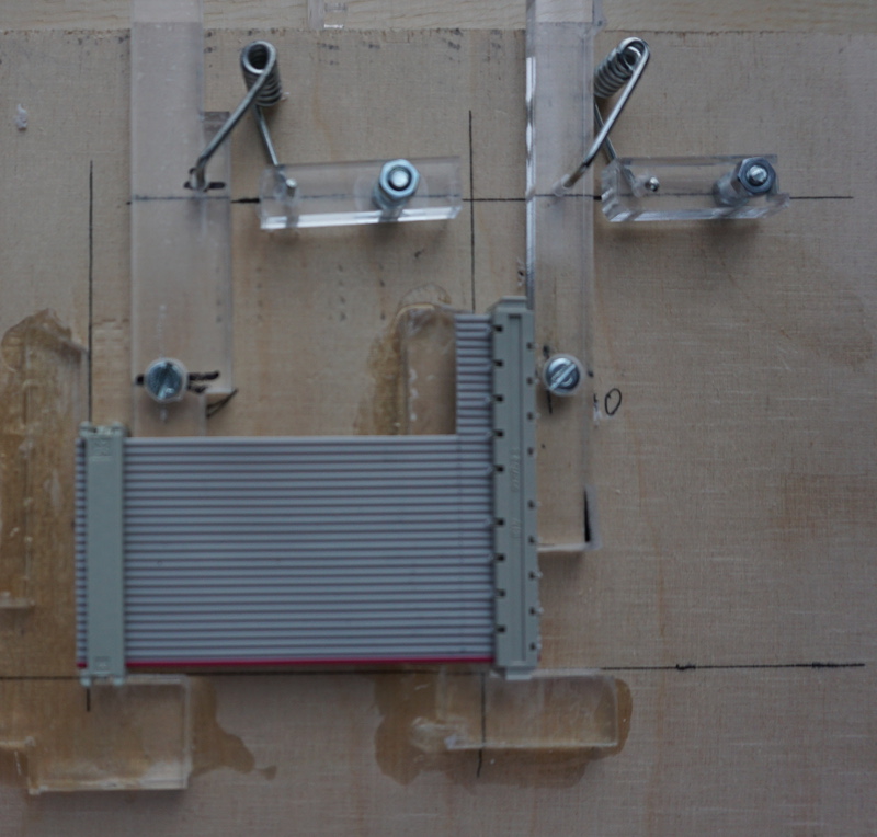
Mounting new connector cables from raspberry to adapter board needs 15 new assemblies. For this task, a tool was assembled from some scrap acryl material I found from some recent laser cut orders.

operation

Two brackets position the connectors, and with two levers the connectors are fixed. The springs are from two pegs. The brackets are glued to plywood base with acryl-glue. This allows to assemble the cables in reproduceable quality.

windiskimager

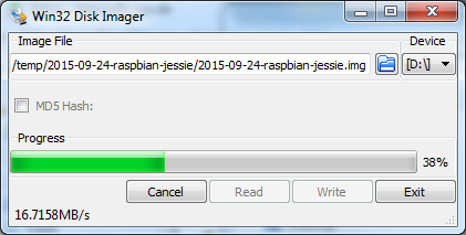
With Win Disk Imager, the SD cards are written. Nice write performance with the new SD cards, almost double the speed of the previous ones used two years ago.

To set up the SD cards, there are ssh connection problems. /etc/ssh/sshd_config needs to be edited to allow root to log in “PermitRootLogin yes”. This made the automatic remote setup procedures run.

Here some ready to use switches.

switches

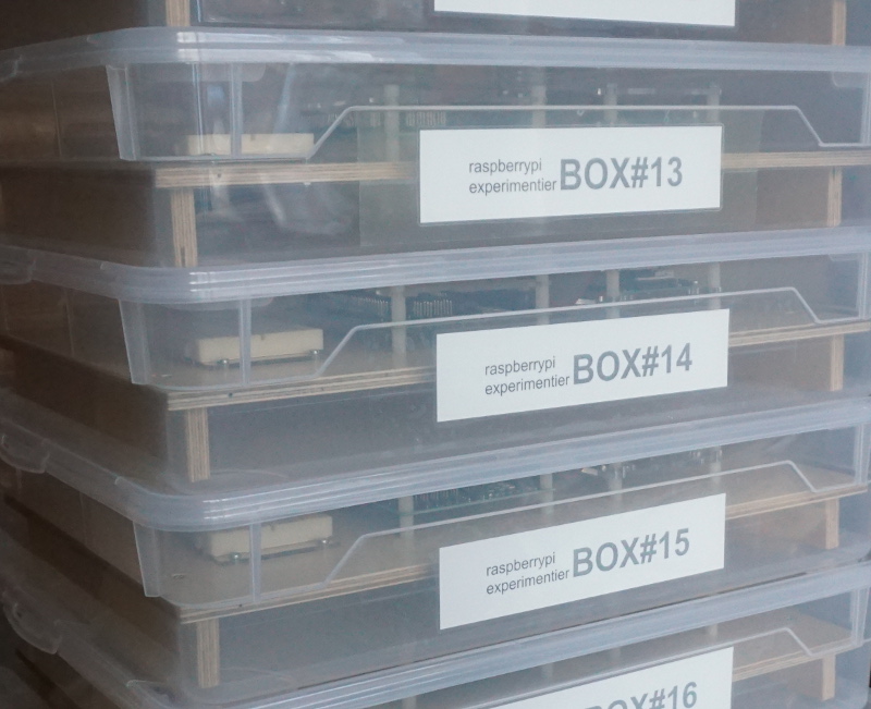
And finally (drum fill) the boxes are ready for school.

boxen

Zusatzaufgabe scratch, Labyrinth

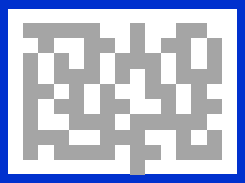
Einen Weg aus einem Labyrinth zu finden ist keine einfache Aufgabe. Es gibt verschiedene Typen von Labyrinthen, das hier gezeichnete ist eine freundliche Variante, die keine Rundwege enthält.

Die Wege sind dunkel gezeichnet und der Ausgang ist am Rand.lab_2

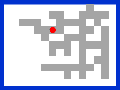
Die Aufgabe ist, dass eine kleine Figur den Weg zum Ausgang findet.stage_seek

Einige Beispiele für Wege sind in dem Beispielprogramm Labyrinth enthalten, siehe Bühne.
Die Rastergrösse ist 30 Pixel in dem Beispiel.

Das Sprite ‘seeker’ aus dem Beispiel hat die richtige Grösse für die Wege. Diese Figur kann auf einem Weg positioniert werden und durch Klick auf die Figur wird diese auf dem Weg zentriert.

Ab diesem Punkt beginnt die Aufgabe: schreibe ein Programm, das den Weg aus dem Labyrinth findet. Egal wo die Figur positioniert wird.

Schritt1: Beispielprogramm Labyrinth laden.
Schritt2: Welche Möglichkeiten gibt es, den Weg aus einem Labyrinth zu finden ?
Schritt3: Programmiere den Lösungsablauf und überprüfe mit verschiedenen Startpunkten und Hintergründen, ob das Programm funktioniert.

Hinweise: im Internet gibt es einige Beschreibungen, wie man aus Labyrinthen entkommen kann.

Die Aufgabe ist schwierig. Wenn auch die Lösung dann mit etwa 30 Blöcken nicht sehr gross wird.

Das Beispiel wurde in Anlehnung an http://www.inf-schule.de/programmierung/scratch/algorithmen/uebungen entwickelt.

Zusatzaufgabe scratch, Malprogramm

Schreibt ein einfaches Malprogramm. Mit den Pfeiltasten soll ein kleiner Punkt bewegt werden können. Mit der Leertaste soll ein Stempelabdruck erzeugt werden können.

Also Schritt 1: Bewegen mit den Cursortasten, Stempeln mit der Leertaste. Erst wenn das funktioniert, dann erst den zweiten Schritt beginnen.

Der zweite Teil der Aufgabe ist schwieriger: fügt eine Abspielfunktion hinzu, welche die Punkte nocheinmal wiedergibt wie im Video.

Schritt 2: Aufzeihnen und Abspielen zufügen.

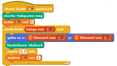
Dazu zwei Listen anlegen (x und y) und die Positionen  des Punktes hinzufügen beim Stempeln.
x_array

Für das Abspielen dann den ersten, zweiten, dritten Eintrag abholen und den Punkt neu positionieren und stempeln.

x_replay

Klar ? Ausprobieren !

Zusatzaufgabe scratch, Grundrechnen

Grundrechenarten üben, erst mal einfach, dann kompliziert.

Einfach:

Schreibt eine Anwendung, mit der jüngere Schüler die Grundrechenarten üben können.

(1) das Programm soll Aufgaben anzeigen, z.B. 3+4. Der Schüler gibt dann die Antwort ein. Wenn richtig, dann Punkte hochzählen und ein Lob ausgeben !

Benutzt Zufallszahlen für die beiden Zahlenwerte. Und Zufallszahlen für den Operator +, -, *, /. (Das ist eine kleine Denksportaufgabe, wie man mit Zufallszahlen den Operator auswählt.)

Und jetzt wird es komplizierter:

(2) Der Bereich der Eingabezahlen soll zwischen 1 und 10, 0 und 50, -10 und 100 sein. Das soll auf der Bühne umschaltbar sein.
(3) Da das Programm für jüngere Schüler ist, sollen die Ergebnisse der Subtraktionen immer grösser oder gleich 0 sein. Die Divisionen sollen immer ganzzahlige Ergebnisse ergeben.
(4) Wenn es Fehler gibt, dann soll genau diese falsch eingegebene Aufgabe später nochmals ausgegeben werden.

Mit der Anforderung (1) anfangen, dann (2). Die Anforderung (3) ist schon schwieriger und die (4) ist schon recht kompliziert.

Zusatzaufgabe scratch, Geometrie

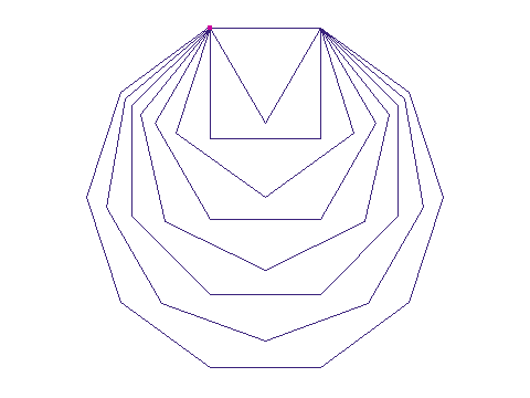
Geometrie mal praktisch: zeichne ein Dreieck, Viereck, Fünfeck, Sechseck, Siebeneck, Achteck, Neuneck und Zehneck. So wie hier dargestellt:

stage_N

Darf auch gerne etwas bunter sein !

Hier kommt das Linienzeichnen zur Anwendung.

Diese Aufgabe ist aus http://www.scratch.ie/sites/all/themes/scratch_theme/resources/newworkbook/Module5.pdf entnommen.


Zusatzaufgabe scratch, Flächen

Flächenermittlung einer unregelmässigen Figur.

Flächen von Figuren kann man berechnen, wenn es Rechtecke, Quadrate, Kreise oder ähnlich sind, Bei unregelmässigen Figuren ist das Ausrechnen meist nicht möglich. Man kann dann z.B. ein Millimeterpapier drüberlegen und die Kästchen abzählen.

Mit dem Computer kann man die Pixel abzählen, und hier ist die Aufgabe dazu.

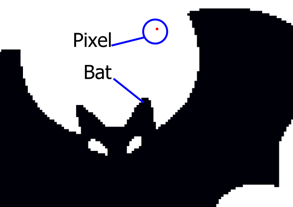
Wie macht man das: Die Pixel-Fläche eines Sprite soll abgezählt werden. Ein zweites Sprite wird zum Abmessen verwendet. Das zweite Sprite ist möglichst klein, also nur ein Pixel gross.

Alle Gruppen verwenden die Fledermaus, deren Pixel-Fläche bestimmt werden soll.

bat_stage_explained

Man bewegt das Pixel-Sprite zeilenweise über die Bühne und wenn das Pixel die Fledermaus berührt, dann erhöht man einen Zähler. Wenn dann das ganze Bild abgetastet ist hat man die Fläche in Pixeln ermittelt.

Damit das nicht allzu lange dauert sollte man nur die Koordinaten (-100, -100) bis (100, 100) abtasten.

Also

– Fledermaus, Bat importieren.
– neues Sprite (nur ein Pixel!), rot ist ganz gut, damit man das kleine Pixel überhaupt sieht.
– Sprite in Zeilen bewegen, im mittleren Bereich des Bildschirmen (-100,-100) bis (100,100). Die Bat muss in diesem Bereich positioniert werden.
– Nach jeder Bewegung des Pixels einen Stempelabdruck erzeugen. Damit man sieht, wie das Programm funktioniert.
– Das Programm läuft relativ lange. Das braucht etwas Geduld. Im Präsentationsmodus läuft das Programm schneller und noch schneller, wenn die Variablen nicht eingeblendet werden.

Das Programm muss überprüft werden. Dazu legt man in der Bat-Sprite ein zweites Köstüm mit einem Rechteck an und berechnet dessen Fläche. Dann lässt man das Programm laufen und das Ergebnis sollte dasselbe sein wie die Rechnung.

Wieviele Pixel ist die Fledermaus gross ?

Wieviele Bewegungen muss das kleine Pixel machen ?

Wie lange dauert das Scannen ? (Benutze die Stoppuhr um das zu ermitteln).

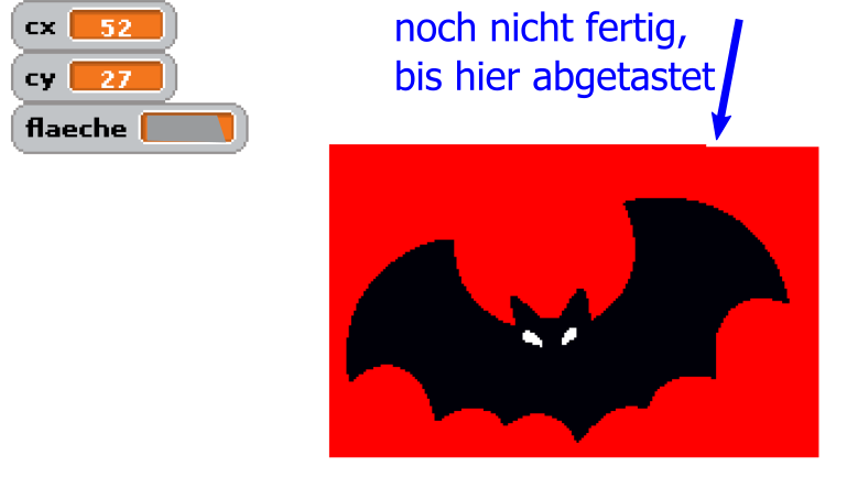
bat_scan_progress

Bühne während des Abtastens. Spooky !

Flächenermittlung MonteCarlo-Methode

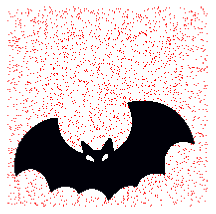
Das Abscannen dauert sehr lange, ist aber genau. Es gibt schnellere Verfahren, die dafür ungenauer sind. Dabei wird nicht mehr zeilenweise abgetastet, sondern das Pixel wird mit Zufallszahlen im Bereich (-100, -100) und (100,100)  positioniert. Dann werden nur wenige Pixel gemessen, hier z.B. nur 3000 Pixel.

Wegen der verwendeten Zufallszahlen werden solche Verfahren nach einer Stadt benannt, in der es ein Spielkasino gibt.

Das Ergebnis ist nicht ganz genau, aber deutlich schneller als das Abtastverfahren. Aber es benötigt im Vergleich zum Scannen weniger als in Zehntel der Zeit.

bat_mc_3000

Monte Carlo-Verfahren, 3000 Punkte

Das Ergebnis ist nur um ein Prozent ungenau. Dafür, dass die Rechenzeit sehr viel kürzer ist ist das sehr gut.

Aufgabe: Ermittle die Fläche mit dem Zufallsalgorithmus.
– positioniere das Pixel 3000 mal zufällig in der x-Achse und y-Achse in (-100, -100) bis (100,100).
mc_position
– Zähle, wie oft das Pixel die Fledermaus berührt in einer Variable ‘ci’.
– Die Fläche ist dann ca (201*201) * ci / 3000. Warum 201 ?

Sense Hat, Astro Pi connected to scratch

Sense Hat (announcement by raspbery pi foundation) is an add on board for PI2, which supports environmental sensors for temperature, pressure and humidity. There is an IMU-sensor included. And a fancy 8×8 RGB-LED matrix. And a small joystick which provides cursor keys and the enter key for the center button.

The software to drive this board is wrapped in a python API. This APi is handy to be used for scratchClient and connect it to scratch.

The adapter is adapter.senseHat_adapter.SenseHat_Adapter.

LED Matrix

Events are ‘clear’, setPixel_xy’ and ‘clearPixel_xy’.

‘clear’ is pretty straightforward and clears the matrix to blank.

The pixel operations need variables to be set before the setPixel can be performed.

procedureCall
x and y position needs to be set and the color needed. The event sense_led_xy_on is mapped to setPixel_xy by scratchClient. This mapping is done in the configuration for this adapter (scratchClient/scratch/senseHat/config_senseHat.xml).

        <input name= 'clear'>
            <broadcast name='sense_led_clear'/>
        </input>
        
        <input name= 'setPixel_xy'>
            <broadcast name='sense_led_xy_on'/>
        </input>
        
        <input name= 'clearPixel_xy'>
            <broadcast name='sense_led_xy_off'/>
        </input>

The commands available in scratch are the <broadcast/> elements. These all have the prefix ‘sense_’.

Color supports basic colors in plain english (red, green, white, blue, and some more) and ‘#aabbcc’ which is hex notation in red, green blue. In the  scratchClient documentation are the details, look for the ‘colorType’-definition in chapter ‘Adapter Data Types’ .

In my experiments, I found that small rgb-values for the LED, e.g. #030303, which is red=3, green=3, blue=3 are not displayed, but leave the LED dark. Obviously the API is doing some gamma correction and discards small values. Try higher values if you run into this problem. #303030 seem to be smallest values available.

For the clearPixel call, no color needs to be set.

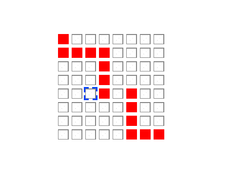
There is a scratch sample application scratchClient/scratch/senseHat/sense_hat_led.sb which allows to set/clear pixel in a (hopefully) intuitive way. Move the blue cursor mark with cursor keys and toggle the LED by blank key.

led_control

Stage printout

The joystick on senseHat can be used to move the cursor around. Unfortunately the center button sends ‘enter’, which is the ‘green flag event’ in scratch and restarts the code. Thus the toggle LED is mapped to the blank bar on keyboard for this sample.

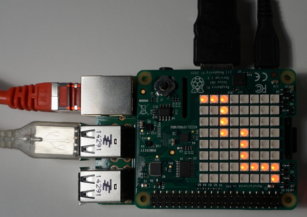
led-matrix

A LED pattern, camera shutter time 1/60 sec

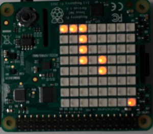
led-matrix-2

Same LED pattern, camera shutter time 1/100 sec displaying only part of the LED

Took me  a while to identify the problem in the second photo: the exposure time was 1/100 sec, so the refresh rate of 80Hz for the LED produces fake ‘missing LED’ on the sense hat.

Environmental Sensors

The humidity, pressure and temperature values are sent at a limited frequency to scratch. And only when values change. For this adapter, the precision of values sent is limited to one decimal digit. This reduces communication effort and system load by 10 percent.

The temperature value and dependent from this the humidity sensor suffers from heating of the hat board by the primary processor. On my desktop, the temperatures reported have been prox 10 degree too high. There are reports of people who separated the Pi and hat by a ribbon cable and got better results.

IMU Sensor

The gyro, accel and compass sensor contribute to the orientation signals, which are sent as orientation_yaw, orientation_roll and orientation_pitch to scratch. These values are quite stable. These values also are sent only at a limited frequency and reduced precision to one digit number. But 1/10 degree is good for most purposes.

Installation of prerequisite software

The board needs software to be installed. See the installation instructions on the API side

Start scratchClient

cd ~/scratchClient
sudo python src/scratchClient.py -c scratch/senseHat/config_senseHat.xml

Remote scratch connection, 2×3 multipanel setup

With scratchClient, it is possible to connect multiple scratch instances with events. ScratchClient can combine this feature with other adapters, as GPIO or alike.

To demonstrate a ‘chain reaction’ type application, I have connected six scratch screens in a 2*3-array to have a red dot traverse the screens.

As I do not own 6 hdmi-monitors for scratch, I have collected 6 vnc-sessions with 600*400-resolution on a desktop computer. The video is taken from this machine.

Each scratch instance sends a specific start broadcast to the next scratch instance to trigger the display-move-hide sequence there. So Instance 0 sends ‘start_1’, instance 1 sends ‘start_2’ and so on. Instance 5 sends ‘start_0’ and the sequence starts again.

The sample is in the scratchClient-distribution, scratch/chainReaction-folder. If you want to run this sample, you need six raspberry computers. Start scratch/chainReaction/reaction_0.sb on each of the raspberryPi. Change the value of ‘whoami’ to 0, 1, 2.. 5 and arrange the screens in

0, 1, 2
5, 4, 3

order.

On one of the computers, the scratchCommunicationServer needs to be started.

cd  ~/scratchClient
python src/scratchCommunicationServer.py

For each of the computers, there is a distinct computer-specific config script. Adjust the

 <parameter name="server" value="192.168.2.90" />

in the config-files to match the ip-address of the server computer.

For computer 0, use config_start_0.xml:

cd  ~/scratchClient
sudo python src/scratchClient.py -c scratch/chainReaction/config_start_0.xml

and start scratchClient on other computers with config_start_<N>.xml, N=1..5.

The remote connection adapter can be combined with other adapters like GPIO or whatever needed. This is the reason to start the python application with sudo.

The current configuration combines the remote communication adapter with a GPIO output on GPIO18. This is a feature unique to scratchClient.