Category Archives: Uncategorized

Door closing speed analysis

The entry door in the house I live has an automatic door closer, which started to close the door faster and faster over time and slammed the door with an incredible sound. There is the possibility to to adjust closing speed with two screws on the door closer for the overall closing speed, and the speed for the final few degrees.

As tuning the system with the screws is quite difficult (a few degrees of turning the screws changes closing times by 10 secs), I added a speed recording device temporarily to the door and recorded the closing speed. And I wanted to use the wireless capabilities of the MKR100 to avoid having a lot of cables in a public area.

The door angle was measured with a simple potentiometer, uses the ADC in the  MKR1000 processor and sends the measurement values with a rate of 100 samples per second to a host computer.

door

The chart shows in blue the original closing action, in black the last two records. Horizontal axis is time. The ascending slope is decreased on the black lines, indicating lower speed. And especially the last few degrees move slower and avoid the ‘big bang’ of the door.

door2

The measurement device is temporarily clipped to the door.

door_device

The acryl rod with the small parallel vice form the anchor point for the potentiometer.

A closeup of the device shows the details

  • the MKR100 is mounted on a prototyping board.
  • Three LED display wireless connection status ‘connect to access point’, ‘access to socket’, ‘operational’.
  • The LiPo battery is on the back.
  • The adapter is 3d-printed.

door_device_2

On the host computer, a python program opens a socket and receives the data. With TKinter, the data are displayed.

Scratch, Inconsistent behavior of how data are sent to remote sensor protocol

Scratch, Inconsistent behavior of how data are sent to remote sensor protocol

Related to the scratch optimizations performed by Tim Rowledge the last weeks,  I have investigated my scratchClient and removed some bottlenecks. In some cases, it used more CPU as scratch itself. Now, the ping-pong-performance test runs in 50ms for one cycle.

When you do things like this, the next question is whether all values are handled correctly. This is the starting point for the following experiments.

You do not need a sophisticated test software to execute the experimennts. A simple “telnet localhost 42001” just displays what is going on, at least the send-to-the-outside part of the story. You need to enable the remote server inside scratch first. Do this by /sensing / rightclick on ‘slider’ sensor value / enable remote sensor connections. In current scratch, you need to disable this first, then enable. In nuScratch or in windows, just enable. I repeated these things on windows, where I used putty in raw mode for the telnet part.

Be careful in typing in characters into the telnet session. Scratch will try to interpret these for the protocol. After some characters, you receive an squeak error popup. There is no recovery, you need to restart scratch then. Think there is no robust error recovery strategy for the receiver part of the protocol, but this is not the topic here.

Make a global variable ‘for all sprites’, named ‘a’. The name does not matter, but ‘a’ is simple and short for now.
Run the following script:

repeat

When a was ‘0’ initially, you receive
sensor-update “a” 1 sensor-update “a” 2 sensor-update “a” 3
This is ok.

Next sample:

multiple_set

The result is
sensor-update “a” 2
Which is not very good. The intermediate separate set-values are ignored. When repeating the execution, there are no more sensor-updates sent out.

Now add wait statement to the script.

multiple_set_wait

Now the result is
sensor-update “a” 0 sensor-update “a” 1 sensor-update “a” 2
This is as expected. This also works, when the delay is set to ‘0’.

Some change-by-blocks in a sequence do behave even different. The last value is propagated.
This is done to find out if the ‘change by’ block has special handling.

multiple_inc

The result is, when executed multiple times
sensor-update “a” 44 sensor-update “a” 47 sensor-update “a” 50 sensor-update “a” 53
So only every third update is propagated.

Last one, embrace “each set a to something” in a while(1)-loop

while

This results, as expected, are
sensor-update “a” 66
sensor-update “a” 67
sensor-update “a” 68
sensor-update “a” 69
sensor-update “a” 70
sensor-update “a” 71

Conclusion

Sensor protocol sends out multiple updates in a sequence only when control blocks are in between. Multiple update blocks in a sequence seem to get optimized in a strange way, and not consistent for ‘set value’ and ‘change-value’.
This is same behavior in win-1.4-scratch and RPi-1.4-scratch and RPi-1.4-beta.

My original assumption was, that there is a ‘previous-value’ for each variable, and when a change is detected, then the value is propagated. Current implementations do not work this way.

Current behavior is difficult to explain for kids working with scratch.

Raspberry optimized scratch, performance beta4

Since some weeks, a new beta scratch version for RPi is around, announced on raspberrypi.org.

The work done by Tim Rowledge is in the area of performance. First impression is ‘it is faster’ in editing and runtime. So it is time to measure some performance numbers.

I measured timings for three systems:

  • RPi-1.4-scratch is current scratch/squeak as on raspian, clocked at 1GHz.
  • RPi-1.4-beta is current version of beta scratch (2014-06-13).
  • win-1.4-scratch: To compare with a more powerful system, I have run some of the tests on a laptop machine, running scratch 1.4 from scratch.mit.edu, windows 7, 4 core processor 2.2GHz

Update: jamesh asked to repeat the tests with ‘HW cursor implementation for X’ xf86-video-fbturbo – video driver. Sounds complicated, but installation was straightforward. The tests executed with this modified X-system are marked with ‘X’

  • RPi-1.4-scratch-X, modified X  running RPi-1.4-scratch
    RPi-1.4-beta-X , modified X running RPi-1.4-beta.

Results

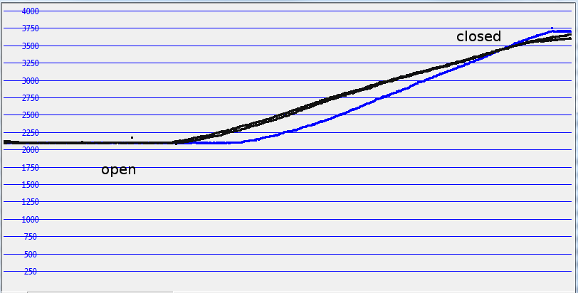
In loops and calculations, the new scratch version on RPi even outperforms my windows-machine running legacy-1.4-scratch from mit.edu. On Pi, it needs only 50% execution time compared to current pi-scratch. This is impressive good.
For the other tests, execution time is down to some 85%, 80%.

One exceptional improvement is in these cases where variables are displayed on stage. This slows down current scratch, but in beta and with the modified X it executes 1o times faster (move2_presentation).

Especially for the graphic operations, improvements are noticeable.

performance_summary_2

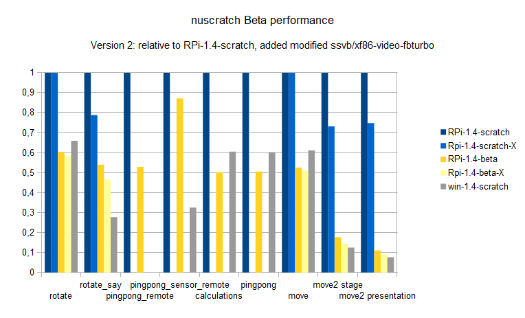
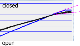
The results are blue, dark yellow for raspbian system, and light blue, light yellow for the modified driver.

The modified driver in X results in better performance, execution times are 0.8 times only in most cases. The quite simple rotate and move-examples do not benefit too much, but whenever it gets crowded on stage it is noticeable.

For scratch remote sensor connections, the improvements are not so impressive and I assume it is based on overall performance optimizations. But the tests show that remote connections for broadcasts or variables need 40 ms for sending or receiving. Which is not bad. The great improvement in pingpong_remote is due to the comparison of presentation mode operations. Here, the RPi-1.4-scratch is much slower in presentation mode. Compared with full-stage mode, this is in the 80% range of other results.

The scratch projects are in performance.zip.
For the scratchClient, see download page.

Graphic system (performance_rotate.sb)

Rotating sprites needs quite a lot of computation power. It needs rotating the sprite by an angle and redisplay the graphics. In order to avoid possible caching of calculated sprite graphics, I have choosen to apply extra ‘one degree’ rotations in between.

RPi-1.4-scratch  10.6 sec
RPi-1.4-beta 8.5 sec

Graphic system 2 (performance_rotate_say.sb)

Displaying the ‘say’-bubble is a challenge. The system needs to look for the solid icon inside the alpha background, and adjust the bubble accordingly.

RPi-1.4-scratch  22.5 sec
RPi-1.4-beta 14.0 sec. This is impressive good.

win-1.4-scratch 6.0 sec

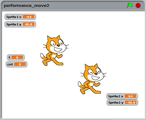
Graphic system move, move2

The move sample I usually explain to the kids in school as a scratch-antipattern: while true; goto x,y; inc x; inc y; endwhile; This works, but movement speed is limited by cpu-usage. The second is movement of two sprites with variable display on stage. This slows down execution speed drastically in RPi-1.4-scratch. In this area, the beta is a class better.

move2

The presentation mode timings are

RPi-1.4-scratch 159.4 sec
RPi-1.4-scratch-X 119.2 sec  using the modified X driver

RPi-1.4-beta 17.6 sec.
RPi-1.4-beta-X 14.3 sec  using the modified X driver


win-1.4-scratch 12.1 sec

Scratch Sensor Network performance (performance_pingpong_remote.sb)

There are many assumptions on remote access for scratch timings. So I took the opportunity to measure some values.

It is not possible to measure time from a broadcast in scratch till it arrives in a remote system. It would need software ‘instrumentation’ inside scratch. But it is possible to send out a broadcast, and wait for a response coming back, using a remote scratchClient.

For the test, scratch script sends broadcast “ping”, and my scratchClient-software responding with “pong”. In scratch, this is repeated 200 times and time recorded.

RPi-1.4-scratch fullscreen 30.3 sec (!)
RPi-1.4-scratch edit mode 18.4 sec

RPi-1.4-beta fullscreen 16 sec.

The legacy scratch in fullscreen needs much longer than in edit mode, although the script animations cost some time. Strange.
The new scratch is 10 percent faster.

What does this mean on IO-Performance ? One event out, one in in 16sec/200 = 80ms or one way in 40ms. This is much faster than reported elsewhere. Not to forget: nothing else running around, no animations or alike.

When you want to run this test on your machine, load my scratchClient software, and use command line

cd ~/scratchClient
sudo python src/scratchClient.py -c config/config_pingpong.py

Scratch Sensor Network performance (performance_pingpong_sensor_remote.sb)

Similiar setup as in the broadcast example, but there are variable values send over the network.

analog

When scratchClient receives the ‘a’-value, it increments it by ‘1 and sends it back.

RPi-1.4-scratch 77.1 sec
RPi-1.4-beta 67.2 sec

win-1.4-scratch 25.0 sec

These values are very close to the broadcast-timings.

The scratchClient is same as for the broadcast test.

Scratch Calculations (performance_calculations.sb)

Simply a loop, and a few calculations.

RPi-1.4-scratch 41.3 sec
RPi-1.4-beta 20.7 sec (checked twice, real fast)

win-1.4-scratch 25.0 sec

Scratch Broadcasts (performance_pingpong.sb)

Sending broadcasts inside scratch. Remote sensor connections are disabled, and code is executed in presentation mode to avoid the script animations during executions.

RPi-1.4-scratch 83.0 sec presentation screen
RPi-1.4-scratch 75.0 sec full stage screen

RPi-1.4-beta 41.9 sec presentation screen
RPi-1.4-beta 84.5 sec full stage screen

win-1.4-scratch 50.0 sec


ADC-328-Board is here

The  boards for the Atmel-328 based ADC board are here. And it works, only the LED connection was on the extra pin used by the 20MHz-version of this design. Corrected in software, already.

See the adc-board post, the capacitive sensor post for application details. The basic design is for a breadboard, but I wanted to have a portable package for this.

Schematic is here, the eagle schematic and board files are in the software package.

To get the board running with scratch, you need my scratchClient software.

Functionality are – with the firmware – 2 adc channels, frequency counter, impulse counter and infrared control. The two rotary encoders are prepared, but not yet coded.

board

The board uses 1206-size SMD components, just the size you can solder without a microscope.

JP1 is usually open, and connects GPIO4 to clock input. See flashing instructions.

SV1 is to the RPi

SV2 is ADC input. 1 = GND, 2 = GND, 3 = ADC0, 4 = ADC1, 5 = VCC, 6 = VCC

SV3 is usually open. It allows to connect RX, TX with those of RPi. It is aligned to allow to connect with two jumpers. I used this mainly for debugging purposes.

SV4 is the frequency measurement input. 1 = GND, 2 = input, 3 = VCC

board

This project is no kickstarter, and I do not sell this pcb.

So setup the parts on a breadboard, and if you like it find one of the reasonable cheap, long delivery time vendors in the world and build your own copy.