The ultrasonic sensor HC-SR04 is a quite inexpensive ultrasonic sensor, well suited for microcontroller applications.
It produces pulse width modulation directly giving the signal run time.
For 1.7m, at sound speed in air of 340m/s, you get 10ms pulse width.
Up to now, my scratchClient software had no ability to support this device. In order to evaluate different approaches to measure pulse width timings in this range, I have set up an arduino board simulating this device with 10ms timing.
The goal was to have around 1000 measurements and look for the distribution of values.
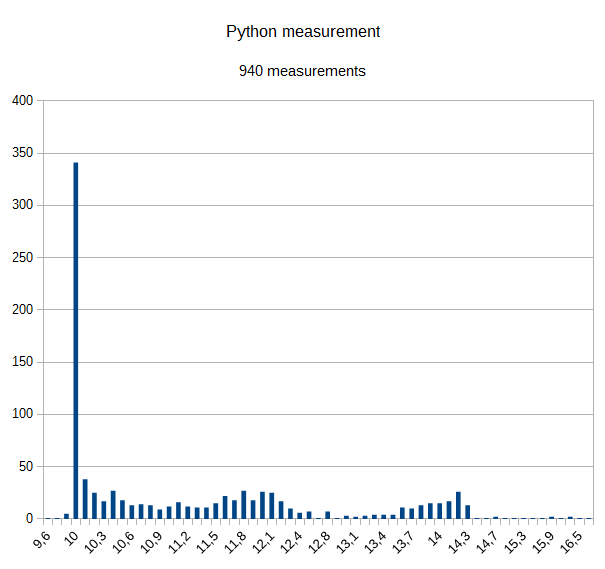
Approach A was to take python code as found on the net. Two loops, first one looking for raising pulse and second one looking for falling pulse.

Results are not very precise.
There are quite a lot of measurements at 10ms, but 2/3 of all results are up to 40% higher; few also till 16,5 ms. This is as expected, as the IO system is slow, and a lot of other things are running in the system in parallel.
Advantage is that there are no additional cost, except some voltage dividers needed.
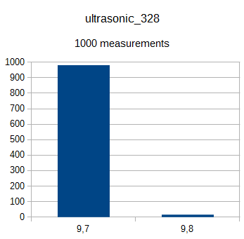
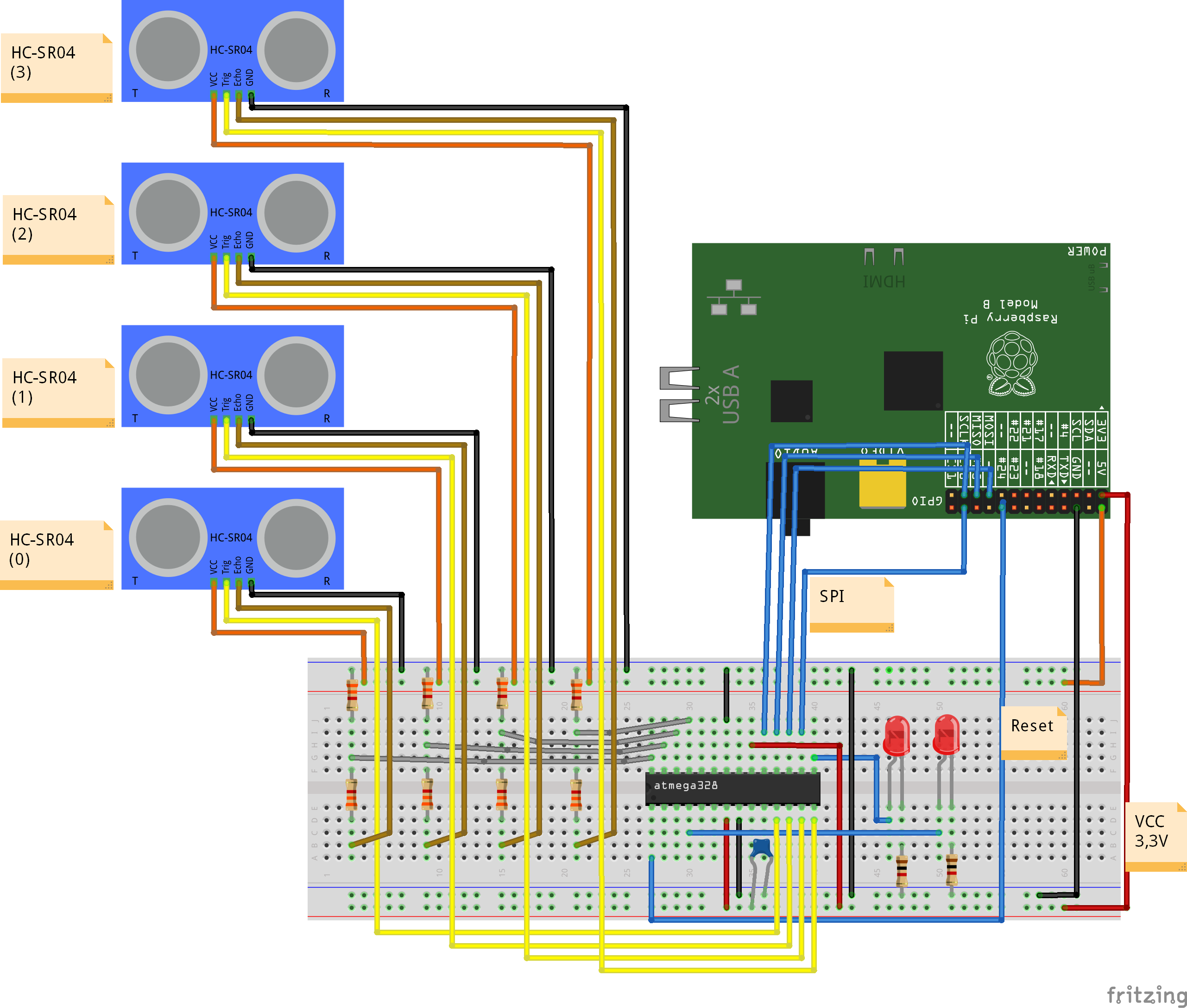
Approach B is a microcontroller subsystem using the atmel 328 chip, sitting on a breadboard and connected with SPI to RPI. The internal oscillator is used for simplicity and reduced cost. This setup is similiar to the adc-setup described in another post.
Time measurement is using the 16 bit timer in 1/64 resolution, yielding 8us values.

Results are pretty nice, although the deviation is 3% from 10.0ms. Most possible this is caused by the free running oscillator running a little bit too fast; some more investigation is needed here to eliminate software errors.
The code is polling the timer, which is fast enough for this application. SPI is handled with an interrupt coded in assembler. This allows up to 240kHz SPI frequency.
The software is completed and supports up to 4 sonic sensors.
Cost is prox 3.5$ per unit, some soldering and some voltage dividers. No difficult software setup needed.
I found other approaches on the net. DMA code, C-Code or alike. Problem here is the complicated software setup (no ready to use solutions) and the difficult integration into the python environment with RPI.GPIO.
The hardware setup is straightforward. Note the 5V on the supply voltage of the HC-SR04. Doublecheck also the ground connection from HCSR04 to breadboard and to Raspberry. This is important to avoid to get 5V into the raspberry inputs.
For the scratch setup, there is a sample configuration with device(0) connected.
cd ~/scatchClient
sudo python src/scratchClient.py -c config/config_hcsr04_atmel328.xml
In scratch, enable remote sensor connections. You receive ‘distance_A’.
For detailed instructions on how to program the atmel processor, see the documentation in the download file on download page. The programming is performed by the raspberry pi with the SPI cabling.
