Author Archives: ghp_Ar7p

Barcode scanner for scratch

barcode

Connecting a barcode scanner to scratch

Some time ago I aquired a barcode scanner, which I use to manage a CD collection based on the EAN-code printed on the packages.

These scanners typically can send codes by emulating HID-class devices. This makes usage from programs quite easy, but you loose input when the program goes to background and other programs get the focus.

Currently I try to bring this code to raspberry pi, using python and pyusb library. This library allows access to usb devices and, very important, can grab devices to be used exclusively by one program. As a side result from this work, I added a barcode scanner adapter to scratchClient.

Install pyusb

Here I found a problem. The usual install did not workwith „pip install pyusb“. This resulted in a ‘backend not found’ exception and „undefined symbol: libusb_strerror“
When I tried to download walac-pyusb-50b1490 from https://github.com/walac/pyusb, this worked, but I had to uninstall the pip-installed code first „sudo pip uninstall pyusb“.

The needed backend packages are already available in raspbian, you can check this with

apt-cache pkgnames | grep libusb

You should find libusb-1.0-0 in the list.

Setup Scanner for USB and CR-suffix

A few preparations are needed with the scanner to enable HID mode. With my scanner I got a handbook with a huge amount of programming codes. You start programming with a ‘start programming’ code, scan the appropriate setup code and exit programming with an ‘end programming’ code.

For my sample, I have setup HID mode, and added exit code/suffix CR. This is needed to detect complete sequences. The adapter in scratchClient relies on this.

Configure idVendor and idProduct

Another preparation is the configuration of idVendor and idProduct in the adapter’s config file. Use the utility enum.py to list the devices available

cd ~/scratchClient
python tools/usb/enum.py

Here the output for my scanner

DEVICE ID 0c2e:0200 on Bus 001 Address 007 =================
bLength : 0x12 (18 bytes)
bDescriptorType : 0x1 Device
bcdUSB : 0x110 USB 1.1
bDeviceClass : 0x0 Specified at interface
bDeviceSubClass : 0x0
bDeviceProtocol : 0x0
bMaxPacketSize0 : 0x8 (8 bytes)
idVendor : 0x0c2e
idProduct : 0x0200
bcdDevice : 0x5881 Device 88.81
iManufacturer : 0x1 Honeywell Scanning and Mobility
iProduct : 0x2 Honeywell Scanning and Mobility Scanner
iSerialNumber : 0x0
bNumConfigurations : 0x1
CONFIGURATION 1: 300 mA==================================
bLength : 0x9 (9 bytes)
bDescriptorType : 0x2 Configuration
wTotalLength : 0x22 (34 bytes)
bNumInterfaces : 0x1
bConfigurationValue : 0x1
iConfiguration : 0x3 HID Keyboard
bmAttributes : 0x80 Bus Powered
bMaxPower : 0x96 (300 mA)
INTERFACE 0: Human Interface Device ====================
bLength : 0x9 (9 bytes)
bDescriptorType : 0x4 Interface
bInterfaceNumber : 0x0
bAlternateSetting : 0x0
bNumEndpoints : 0x1
bInterfaceClass : 0x3 Human Interface Device
bInterfaceSubClass : 0x1
bInterfaceProtocol : 0x1
iInterface : 0x0
ENDPOINT 0x81: Interrupt IN ==========================
bLength : 0x7 (7 bytes)
bDescriptorType : 0x5 Endpoint
bEndpointAddress : 0x81 IN
bmAttributes : 0x3 Interrupt
wMaxPacketSize : 0x8 (8 bytes)
bInterval : 0xa

What you also should check is the iConfiguration to be a HID Keyboard.

For verification open a text editor like leafpad: when scanning a code, this should be entered into the editor as a text string.

Edit config/config_barcode.xml and adjust the vendor/product id there.

In my environment, I use a powered USB hub to connect the scanner.

Start scratchClient

cd ~/scratchClient
sudo python src/scratchClient.py -c config_barcode

The file config/config_barcode.xml is a starting point for a project. Add other adapters as needed.
When scanning barcodes, these are send to scratch. Do not forget to enable remote sensor connections.

scratch_barcode

raspbian 2014-12-24

Pünktlich zu Weihnachten 2014 hat die pi-Foundation einen Update der Oberfläche veröffentlicht.

Die sichtbarste Änderung ist das neue Layout des Desktop mit der Menüleiste am oberen Rand. Ebenfalls auffällig ist, dass es keine desktop-Icons mehr gibt.
Über die Menüleiste am oberen Rand wurde im Forum der pi-Webseite bereits heftig diskutiert.
Da die Bildschirme in letzter Zeit immer mehr in die Breite gehen, ist mir es lieber die Menüleiste am linken Rand zu haben.

Die neue, überarbeitete Version von scratch ‘nuscratch’ ist ebenfalls enthalten. Für den Schulkurs erst mal eine gute Nachricht, da diese Version deutlich schneller ist.
Leider gab es bei der Integration in das System noch einige Probleme. Die Dateiverzeichnisse waren nicht vorhanden, die Hilfetexte funktionierten nicht und auch ein Aufruf aus dem Browser (über einen Link) funktionierte nicht.
Mit

sudo apt-get update
sudo apt-get install nuscratch

kann das jetzt behoben werden. In zukünftigen Versionen ist dann wahrscheinlich gleich richtig.

Diese neuen Versionen von Scratch wurden von mir gründlich getestet. Das Verhalten ist gleich wie die ursprüngliche Version, auch die Anbindung an scratchClient funktioniert korrekt.

Die Tutorials für die Schüler wurden zum Schuljahr H2/2015 angepasst, um die neue Oberfläche zu zeigen. Das Kapitel über die Desktopumschaltung ist deshalb entallen, da es den Umschaltknopf nicht mehr in der Voreinstellung gibt.

Weihnachtskarten mit scratch

Mit scratch kann man  animierte Postkarten machen und Freunden und Bekannten einen Link auf die scratch-webseite mit dem Projekt schicken.

Dann braucht man nur noch auf den Link clicken und die eigene Idee erscheint im Browser.
Hier ist eine Anleitung, wie man das machen kann.

Schritt 1: Erst mal schauen wie man so was macht.

Beispiele ansehen

http://scratch.mit.edu/projects/11806234/
http://scratch.mit.edu/projects/14971587

Schritt 2: bei scratch anmelden

Im Browser scratch.mit.edu aufrufen.
karte_10

„Join scratch“ drücken

username ausdenken (nicht den echten Namen, auf KEINEN Fall).
passwort ausdenken und merken. Oder aufschreiben.

Schritt 3: Projekt erstellen

Bevorzugt auf scratch 1.4, ladbar über http://scratch.mit.edu/scratch_1.4/
Oder auch über die web-Oberfläche.

Speichern

Bitte denkt daran, dass das Projekt nachher von der ganzen Welt gesehen werden kann. Also keine echten Namen, Bilder o.ä. verwenden.

Schritt 5: Projekt teilen

In scratch 1.4 auf ‘Veröffentlichen!’ drücken und ‘Dieses Projekt im Internet veröffentlichen.’ auswählen.
karte_20

Den online Namen von vorher angeben und das Passwort.

Schritt 6: Projekt Link suchen

Auf scratch.mit.edu einloggen. Rechts oben erscheint der Name, ‘My Stuff’ anwählen. karte_30
Dann bekommt man eine Ansicht der eigenen Projekte.

karte_40

Das Projekt anclicken, das Bild links. Man erhält die Projektansicht.

karte_50

Und so sieht das Ergebnis für das Beispielprojekt aus:
http://scratch.mit.edu/projects/39510388/

Eure URL für euer Projekt hat dann natürlich eine andere Projektnummer.

Die URL für das Projekt dann an Freunde und Bekannte schicken. Per email. Oder so.

Schritt 9999: Jemand erhält die email und will sich das ansehen.

Die URL mit dem Browser öffnen. Dann im Browser mit der grünen Flagge starten.

Der Browser muss Flash erlauben, das ist ein Plugin, das für die meisten Umgebungen verfügbar ist.

Was auch noch geht

Den Link auf das Projekt als QR-Code aufbereiten. Da gibt es im Internet einige Seiten, wo man das machen kann. Aber Vorsicht hier: es gibt einige Seiten die eine Registrierung verlangen oder sogar Geld verlangen. Benutzt nur Seiten, die keine Registrierung erfordern und wo man das Bild direkt herunterladen kann.

qr_code_without_logo

Environmental Sensors for scratchClient

The recent months have been busy with preparing new experiments for my
school project, especially one experiment measuring temperatures with TMP36. See
link

When looking in detail to the datasheet of TMP36, there is an accuracy of max
+- 4K (G-Grade device) and +- 3K (F-Grade device). This is not bad for -40 to 125 °C. At 25°C, accuracy is  +- 3K (G-Grade device) and +- 2K (F-Grade device).
Unfortunately the ADC on my adapter board, the MCP3202, uses the
vcc-voltage as reference, which gives additional error for the measurement.
With patch cables, there is also some noise. I twisted signal and ground
line, added some capacity close to the TMP36 power pins and a low pass
filter in the adapter logic. Which reduced, but did not remove the problems.

So I started to look for more precise alternatives. LM35 in combination
with an adc ads1015 and internal precision reference voltage gives better results.
LM35A specs give +-1K over -40 to 110 °C, around 25°C +- 0.5K.

When starting to look for integrated solutions, complex devices like SHT15
come around. Main purpose is to measure humidity, but temperature
measurement is included. +-0.3K around 25°C and +-1.5K in -40 to 90°C are
quite good. I2C is not supported, but a two-wire GPIO protocol is
available. Disadvantage is the high price.

BMP085 is a digital pressure sensor with temperature sensing included. +-2K
accuracy in 0 to 65°C. I2C, internal calibration data in registers, needs
some calculations to correct the raw values.

MAX31855K is used with k-type thermocouples and extends temperature range
to -200 to 1350°C. Note that K thermocouples have about ±2°C to ±6°C
accuracy. SPI interface is easy to use.

And for curiosity, I added a luminosity sensor BH1750 to this collection of
devices.

Scratch integration is ‘as usual’ with adapters, where configuration is
done by xml files.

Hardware interface to the devices (to be more precise: the breakout boards
with the devices, is by I2C, SPI or plain GPIO. For the SHT15, I added a
serial resistor of 1kOhm for the data line to protect against
input-output-mismatches during debug phase of code. For the clock line, this
is not needed, but in general a good idea to a serial resistor there too.
Too expensive this device, to take the risk of burning it away.

These sensors will not be part of the school workshop documentation. Setup
is described in the scratchClient handbook → link.

Sending, Receiving SMS messages with GSM Modem

Recently I bought an instance of adafruit’s SIM800 breakout board ‘fona’. This board allows for sending and receiving of SMS  text messages (and a lot of other functionality, of course. But I covered only the text messages for scratch). For the text messages, I added an adapter for my scratchClient software.
For download and documentation, see [url]http://heppg.de/ikg/wordpress/?page_id=6[/url]

In scratch, a variable ‘sms_out’ is used to send messages, incoming messages are in the sensor value ‘sms_in’. Easy to use, and today I ignored provider cost and have sent me SMS every hour ‘scratch installation still running’. Could be more useful, but is fun when your computer gives you a call.

Connection of fona is by RX, TX to TX, RX of raspberry. You need to remove some getty processes from this line, there are documentations around describing this.

The sim800 uses an AT-protocol, like ‘at+cpin?’, and receives signals like ‘+CPIN: SIM PIN’.
For the initialization of the device, the adapter implements a state machine, which step by step initializes the modem, sets the pin and then waits for action.
Switching the modem on is done by pressing the ‘on’ key on the breakout board. Could be done by using GPIO, but I decided to need some additional access control.

The receiver side oft the serial protocol reads line by line, looks for known names and feeds the state machine with input.

The code is still experimental. There is no buffering for scratch input, so if scratch feeds too fast, there will be lines dropped. But It is not intended as a spam machine… The phone number being called on send events is fixed for the same reason.

If you want to run the software, be sure to have a backup phone which allows to reset the pin (in case it was forgotten to configure the pin in the adapters xml file, it might happen that after a few retries the device is blocked.)
And the manual of the sim800 is useful. Which is 300 pages.


Scratch Connection Status Display

With a new adapter adapter.gpio.GpioStateOutput, it is possible to bring the scratch connection state to GPIO.

When scratchClient is started, the associated GPIO pin is going high. When connection to scratch is established, the pin is blinking slowly. And when scratchClient is terminated, the GPIO is going low.
Just add the configuration für this adapter to your configuration.

    <adapter class='adapter.gpio.GpioStateOutput'  name='state'>
        <description>State display on IKG.IO.9</description>

        <gpio port='IKG.IO.9' alias='state'>
            <default dir='OUT'  default='low' />
            <active  dir='OUT'  default='low' />
        </gpio>
    </adapter>

Please note the naming of the port: these names are configurable. You could use GPIO04 instead, or P1-07 if you prefer board numbering.
For my school workshop, there is an extra LED available, connected all the time, but not used for other IO. This LED sits on the adapter board in a corner and is ideally suited for a state display.

Scratch, Inconsistent behavior of how data are sent to remote sensor protocol

Scratch, Inconsistent behavior of how data are sent to remote sensor protocol

Related to the scratch optimizations performed by Tim Rowledge the last weeks,  I have investigated my scratchClient and removed some bottlenecks. In some cases, it used more CPU as scratch itself. Now, the ping-pong-performance test runs in 50ms for one cycle.

When you do things like this, the next question is whether all values are handled correctly. This is the starting point for the following experiments.

You do not need a sophisticated test software to execute the experimennts. A simple “telnet localhost 42001” just displays what is going on, at least the send-to-the-outside part of the story. You need to enable the remote server inside scratch first. Do this by /sensing / rightclick on ‘slider’ sensor value / enable remote sensor connections. In current scratch, you need to disable this first, then enable. In nuScratch or in windows, just enable. I repeated these things on windows, where I used putty in raw mode for the telnet part.

Be careful in typing in characters into the telnet session. Scratch will try to interpret these for the protocol. After some characters, you receive an squeak error popup. There is no recovery, you need to restart scratch then. Think there is no robust error recovery strategy for the receiver part of the protocol, but this is not the topic here.

Make a global variable ‘for all sprites’, named ‘a’. The name does not matter, but ‘a’ is simple and short for now.
Run the following script:

repeat

When a was ‘0’ initially, you receive
sensor-update “a” 1 sensor-update “a” 2 sensor-update “a” 3
This is ok.

Next sample:

multiple_set

The result is
sensor-update “a” 2
Which is not very good. The intermediate separate set-values are ignored. When repeating the execution, there are no more sensor-updates sent out.

Now add wait statement to the script.

multiple_set_wait

Now the result is
sensor-update “a” 0 sensor-update “a” 1 sensor-update “a” 2
This is as expected. This also works, when the delay is set to ‘0’.

Some change-by-blocks in a sequence do behave even different. The last value is propagated.
This is done to find out if the ‘change by’ block has special handling.

multiple_inc

The result is, when executed multiple times
sensor-update “a” 44 sensor-update “a” 47 sensor-update “a” 50 sensor-update “a” 53
So only every third update is propagated.

Last one, embrace “each set a to something” in a while(1)-loop

while

This results, as expected, are
sensor-update “a” 66
sensor-update “a” 67
sensor-update “a” 68
sensor-update “a” 69
sensor-update “a” 70
sensor-update “a” 71

Conclusion

Sensor protocol sends out multiple updates in a sequence only when control blocks are in between. Multiple update blocks in a sequence seem to get optimized in a strange way, and not consistent for ‘set value’ and ‘change-value’.
This is same behavior in win-1.4-scratch and RPi-1.4-scratch and RPi-1.4-beta.

My original assumption was, that there is a ‘previous-value’ for each variable, and when a change is detected, then the value is propagated. Current implementations do not work this way.

Current behavior is difficult to explain for kids working with scratch.

Raspberry optimized scratch, performance beta4

Since some weeks, a new beta scratch version for RPi is around, announced on raspberrypi.org.

The work done by Tim Rowledge is in the area of performance. First impression is ‘it is faster’ in editing and runtime. So it is time to measure some performance numbers.

I measured timings for three systems:

  • RPi-1.4-scratch is current scratch/squeak as on raspian, clocked at 1GHz.
  • RPi-1.4-beta is current version of beta scratch (2014-06-13).
  • win-1.4-scratch: To compare with a more powerful system, I have run some of the tests on a laptop machine, running scratch 1.4 from scratch.mit.edu, windows 7, 4 core processor 2.2GHz

Update: jamesh asked to repeat the tests with ‘HW cursor implementation for X’ xf86-video-fbturbo – video driver. Sounds complicated, but installation was straightforward. The tests executed with this modified X-system are marked with ‘X’

  • RPi-1.4-scratch-X, modified X  running RPi-1.4-scratch
    RPi-1.4-beta-X , modified X running RPi-1.4-beta.

Results

In loops and calculations, the new scratch version on RPi even outperforms my windows-machine running legacy-1.4-scratch from mit.edu. On Pi, it needs only 50% execution time compared to current pi-scratch. This is impressive good.
For the other tests, execution time is down to some 85%, 80%.

One exceptional improvement is in these cases where variables are displayed on stage. This slows down current scratch, but in beta and with the modified X it executes 1o times faster (move2_presentation).

Especially for the graphic operations, improvements are noticeable.

performance_summary_2

The results are blue, dark yellow for raspbian system, and light blue, light yellow for the modified driver.

The modified driver in X results in better performance, execution times are 0.8 times only in most cases. The quite simple rotate and move-examples do not benefit too much, but whenever it gets crowded on stage it is noticeable.

For scratch remote sensor connections, the improvements are not so impressive and I assume it is based on overall performance optimizations. But the tests show that remote connections for broadcasts or variables need 40 ms for sending or receiving. Which is not bad. The great improvement in pingpong_remote is due to the comparison of presentation mode operations. Here, the RPi-1.4-scratch is much slower in presentation mode. Compared with full-stage mode, this is in the 80% range of other results.

The scratch projects are in performance.zip.
For the scratchClient, see download page.

Graphic system (performance_rotate.sb)

Rotating sprites needs quite a lot of computation power. It needs rotating the sprite by an angle and redisplay the graphics. In order to avoid possible caching of calculated sprite graphics, I have choosen to apply extra ‘one degree’ rotations in between.

RPi-1.4-scratch  10.6 sec
RPi-1.4-beta 8.5 sec

Graphic system 2 (performance_rotate_say.sb)

Displaying the ‘say’-bubble is a challenge. The system needs to look for the solid icon inside the alpha background, and adjust the bubble accordingly.

RPi-1.4-scratch  22.5 sec
RPi-1.4-beta 14.0 sec. This is impressive good.

win-1.4-scratch 6.0 sec

Graphic system move, move2

The move sample I usually explain to the kids in school as a scratch-antipattern: while true; goto x,y; inc x; inc y; endwhile; This works, but movement speed is limited by cpu-usage. The second is movement of two sprites with variable display on stage. This slows down execution speed drastically in RPi-1.4-scratch. In this area, the beta is a class better.

move2

The presentation mode timings are

RPi-1.4-scratch 159.4 sec
RPi-1.4-scratch-X 119.2 sec  using the modified X driver

RPi-1.4-beta 17.6 sec.
RPi-1.4-beta-X 14.3 sec  using the modified X driver


win-1.4-scratch 12.1 sec

Scratch Sensor Network performance (performance_pingpong_remote.sb)

There are many assumptions on remote access for scratch timings. So I took the opportunity to measure some values.

It is not possible to measure time from a broadcast in scratch till it arrives in a remote system. It would need software ‘instrumentation’ inside scratch. But it is possible to send out a broadcast, and wait for a response coming back, using a remote scratchClient.

For the test, scratch script sends broadcast “ping”, and my scratchClient-software responding with “pong”. In scratch, this is repeated 200 times and time recorded.

RPi-1.4-scratch fullscreen 30.3 sec (!)
RPi-1.4-scratch edit mode 18.4 sec

RPi-1.4-beta fullscreen 16 sec.

The legacy scratch in fullscreen needs much longer than in edit mode, although the script animations cost some time. Strange.
The new scratch is 10 percent faster.

What does this mean on IO-Performance ? One event out, one in in 16sec/200 = 80ms or one way in 40ms. This is much faster than reported elsewhere. Not to forget: nothing else running around, no animations or alike.

When you want to run this test on your machine, load my scratchClient software, and use command line

cd ~/scratchClient
sudo python src/scratchClient.py -c config/config_pingpong.py

Scratch Sensor Network performance (performance_pingpong_sensor_remote.sb)

Similiar setup as in the broadcast example, but there are variable values send over the network.

analog

When scratchClient receives the ‘a’-value, it increments it by ‘1 and sends it back.

RPi-1.4-scratch 77.1 sec
RPi-1.4-beta 67.2 sec

win-1.4-scratch 25.0 sec

These values are very close to the broadcast-timings.

The scratchClient is same as for the broadcast test.

Scratch Calculations (performance_calculations.sb)

Simply a loop, and a few calculations.

RPi-1.4-scratch 41.3 sec
RPi-1.4-beta 20.7 sec (checked twice, real fast)

win-1.4-scratch 25.0 sec

Scratch Broadcasts (performance_pingpong.sb)

Sending broadcasts inside scratch. Remote sensor connections are disabled, and code is executed in presentation mode to avoid the script animations during executions.

RPi-1.4-scratch 83.0 sec presentation screen
RPi-1.4-scratch 75.0 sec full stage screen

RPi-1.4-beta 41.9 sec presentation screen
RPi-1.4-beta 84.5 sec full stage screen

win-1.4-scratch 50.0 sec


ADC-328-Board is here

The  boards for the Atmel-328 based ADC board are here. And it works, only the LED connection was on the extra pin used by the 20MHz-version of this design. Corrected in software, already.

See the adc-board post, the capacitive sensor post for application details. The basic design is for a breadboard, but I wanted to have a portable package for this.

Schematic is here, the eagle schematic and board files are in the software package.

To get the board running with scratch, you need my scratchClient software.

Functionality are – with the firmware – 2 adc channels, frequency counter, impulse counter and infrared control. The two rotary encoders are prepared, but not yet coded.

board

The board uses 1206-size SMD components, just the size you can solder without a microscope.

JP1 is usually open, and connects GPIO4 to clock input. See flashing instructions.

SV1 is to the RPi

SV2 is ADC input. 1 = GND, 2 = GND, 3 = ADC0, 4 = ADC1, 5 = VCC, 6 = VCC

SV3 is usually open. It allows to connect RX, TX with those of RPi. It is aligned to allow to connect with two jumpers. I used this mainly for debugging purposes.

SV4 is the frequency measurement input. 1 = GND, 2 = input, 3 = VCC

board

This project is no kickstarter, and I do not sell this pcb.

So setup the parts on a breadboard, and if you like it find one of the reasonable cheap, long delivery time vendors in the world and build your own copy.

Atmel atmega328 used as AD-Converter for Raspberry Pi

[german]

see also: Arduino UNO, NANO connected to Scratch

Atmel 328-Prozessor used as AD-Converter

The microcontroller ATmega328P in DIL-package can be used on a breadboard.

This controller has many build-in functions, as ADConverter, timers SPI and more.
The Arduino boards use this controller, making it very popular and many literature is available.
The ADC has 10Bit resolution and in DIP package there are 5 channels available.

Wiring to Raspberry Pi is quite simple. The firmware can be programmed directly from RPi, no programming device needed. The focus of this article is not the programming of the device. The needed firmware is attached to the samples.
Cost of the devive are comparable to simple ADConvertes and are about 4€.

Disadvantage is the more complex setup needed.

On the download page, I provide a firmware which can read two AD-channels and to control a LED. More functions are planned, as frequency measurement, infrared control or rotary encoders.

The firmware of the controller can be programmed with the RPi. No extra flashing hardware is needed.
Prerequisite is that the controller has the internal 8MHz oscillator enabled. This is factory preset.
Basic setup of the controller is defined by ‘fuses’, especially the setup of the oscillator used. Without a working oscillator, programming is not possible.
If you get an already flashed device, e.g. prepared to be used in an arduino board, these will have internal oscillator shut off. In this case, reading out the software will not work. Workaround is to activate GPIO#4 of RPi as a clock source and connect to the 328. See attachments for a short tutorial. Or to use a flashing hardware.
Caution: when you use a device from an arduino board it is likely that the bootloader is overwritten. There is no simple way back.

parts list

  • ATmega 328 P-PU (DIL-package)
  • breadboard
  • precision socket for the processor. DIL 28 pin, 0.3 wide. Insert the socket to the breadboard, and insert the controller into socket. The controller can be used directly, but with the socket insertion and removal is simpler.
  • LED. The longer wire is the anode and is the ‘positive’ side.
  • resistor 1kOhm
  • capacitor ceramik 100nF, min 10V
  • trim potentiometer for test
  • cables f-m, 7 or 8 pieces
  • wires for breadboard.

Setup procedure

Basic steps are wiring, flashing the controller and activating scratchClient software.

electrical setup

Shut down RPi and disconnect power source.

Place processor on breadboard and connect according to scheme.

VCC 3.3V is taken from from Raspberry.
SPI-connections MISO, MOSI, SCK and SS at CS0 of RPI allow communication.
RESET pin 1 to GPIO24 is needed for flashing in addition to SPI.
LED with serial resistor 1kOhm is connected to PB1, Pin 15
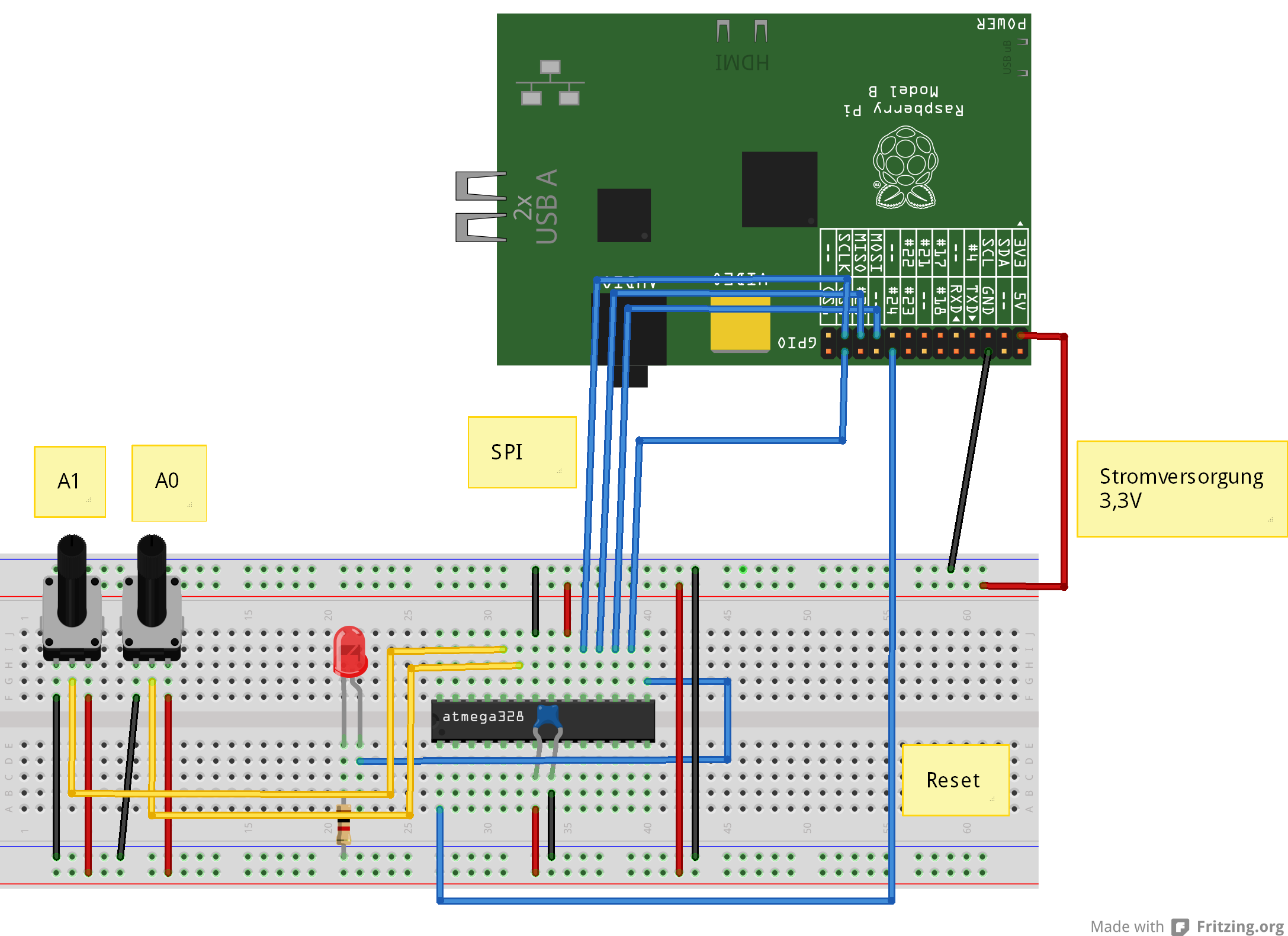
atmel_Steckplatine.
ADC-inputs used are ADC0 and ADC1, Pin 23, 24.

Prozessor im Sockel

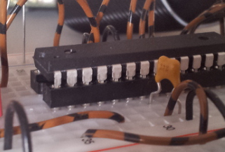
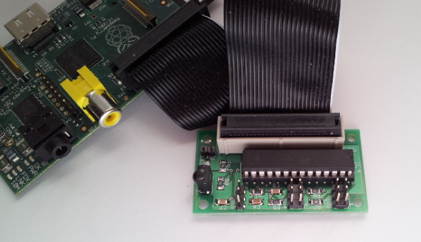
This is how the controller sits in socket on breadboard.


Installing flash software on Raspberry Pi

sudo apt-get update
sudo apt-get upgrade -y
sudo apt-get install python-dev pip
sudo pip install spidev intelhex

Activate SPI driver. Use raspi-config , enable SPI.

Copy the programming software to /home/pi .

Download software and store in /home/pi and unpack “tar xfvz program_328.tar.gz”.

tar xzvf program_328.tar.gz

Validate hardware and software setup

The following steps validate correct cabling and whether flashing the controller is possible.

Read Fuses

cd ~/program_328
sudo python src/program.py -rf

The output should look similiar to

PROGRAMMING_READ_CALIBRATION_BYTE b0 10110000
 PROGRAMMING_READ_EXTENDED_FUSE_BITS ff 11111111
 BODLEVEL0 1
 BODLEVEL1 1
 BODLEVEL2 1
 PROGRAMMING_READ_FUSE_BITS e2 11100010
 CKSEL0 0 ENABLED
 CKSEL1 1
 CKSEL2 0 ENABLED
 CKSEL3 0 ENABLED
 SUT0 0 ENABLED
 SUT1 1
 CKOUT 1
 CKDIV8 0
 PROGRAMMING_READ_FUSE_HIGH_BITS d9 11011001
 BOOTRST 1
 BOOTSZ0 0 ENABLED
 BOOTSZ1 0 ENABLED
 EESAVE 1
 WDTON 1
 SPIEN 0 ENABLED
 DWEN 1
 RSTDISBL 1
 PROGRAMMING_READ_LOCK_BITS ff 11111111

If there are errors (Device not in sync), then either cables are not correct connected or the processor has wrong fuses already programmed.
Check connections. If error persists, then connect external clock.

Read out current code

Another step in validating the setup is to read current code. Should be empty on a brand new device, but is useful to check communication.

cd ~/program_328
sudo python src/program.py -r

The output should look similiar to

python src/program.py -r
 ('read', 'out.hex')
 programming_readCode
 programming_enable
 ('PROGRAMMING_ENABLE', [172, 83, 0, 0])
 (0, [255, 255, 83, 0])
 programming_enable end
 programming_disable
 programming_readCode ende
 ok

Flash testcode to controller

When everything went smooth so far, then it is time to load the first testcode into the controller. It dies nothing but let the LED blink.

cd ~/program_328
sudo python src/program.py -p 328/steckbrett_328_blink.hex

LED should blink slowly.

Program Fuses for oszillator

The controller runs with internal oscillator, but frequency is limited to 1MHz. By setting the correct fuses, the Controller runs with 8MHz.

Please do not program the fuses, if there have been errors in steps before (which are not yet fixed) and the LED is blinking.

cd ~/program_328
sudo python src/program.py -wf

Blinking should stop shortly, and restart quicker, 5 times a second.
Oscillator setup is completed now.

Flash firmware to controller.

Final step is flashing the application firmware. It handles the AD-Conversions, LED-Settings and alike.
cd ~/program_328
sudo python src/program.py -p 328/steckbrett_328.hex

After programming is complete, the LED should blink 8 times. This is part of the RESET routine.

Application – testcode

Blink the LED, long bright, short dark.
cd ~/program_328
sudo python src/test_blink.py

The duty cycle is set by the python code in side Raspberry. This indicates that it is the reaspberry having control.

Read firmware version.
cd ~/program_328
sudo python src/test_get_version.py

Display should show ’93 09′; second number is minor version and can be higher.

Read ADC, Channel 0
cd ~/program_328
sudo python src/test_adc_0.py

Scratch-Connection

When tests for application software work, the next step is the connection to scratch.

cd ~/scratchClient
sudo python src/scratchClient.py -config config/config_adc_atmel328.xml

Configuration can be adjusted in the config file. ADC-channels can be enabled / disabled, or reference voltage can be 3.3-V or the internal reference 1.1V.
The internal reference voltage is useful when an tempperature sensor TMP036 is connected.
The 3.3V-reference is perfect when a potentiometer is connected.

The ADC values are sent with variable names ‘adc_0’ und ‘adc_1’ to scratch, range is 0..1023.
Broadcast commands from scratch to controller are ‘led_off’, ‘led_on’.

SPI-Communication between RPi and Controller

SPI is a synchronous protocol. The Controller as slave has no chance to indicate ‘slower please’ to the master. Therefor, each command from RPi to controller needs to be answered in the time between receiving the first an second byte of a sequence. Otherwise, there will be garbage read back.

This limits transfer speed to 240kHz with the 8MHz controller. With the 20MHz variant, this will be faster.

Appendix: GPIO#4 of RPi as clock-input for 328

Der GPIO#4-Pin can be configured to provide a MHz range clock signal for the controller. The program for this is in bin/-folder. It is based on code from guzunty.org.

Connect GPIO#4 with XCLK-Eingang of controller. Then start program bin/gz_clock_1.92MHz.

cd bin
chmod +x gz_clock_1.92MHz 
sudo ./gz_clock_1.92MHz

While this program is running, execute read/write of fuses in a second terminal window.
Then disconnect GPIO#4.

Update history:
2014-04-01 Fixed connections of LED