The workshop in school grew by a few kids, and there is the need for additional boxes. As these are no ready to buy products, there again was some design, procurement, a lot of parcels dropping in and some work in preparing plywood, electronics and cases for the PI2.
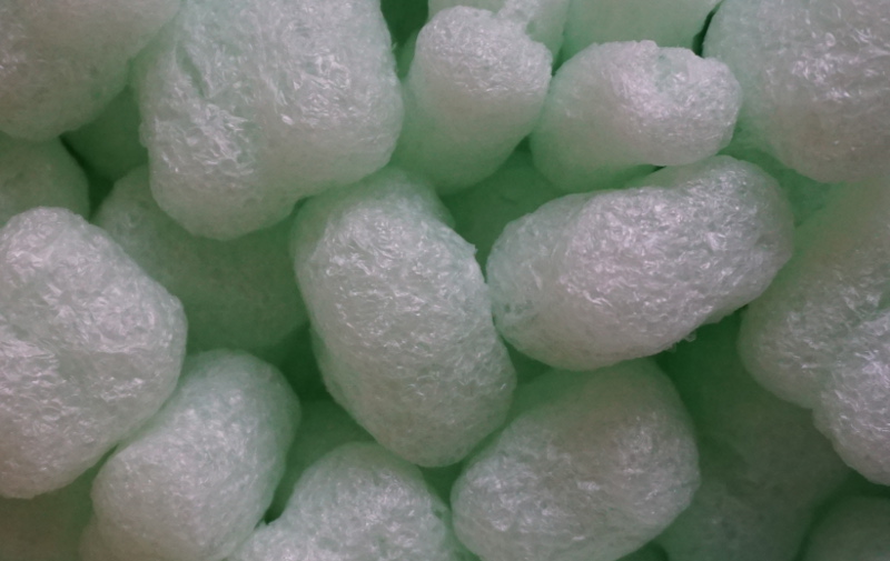
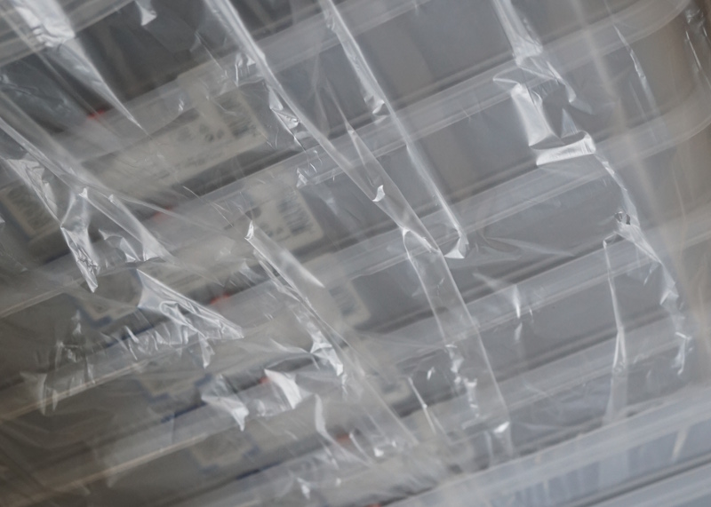
A lot of packaging material floating around.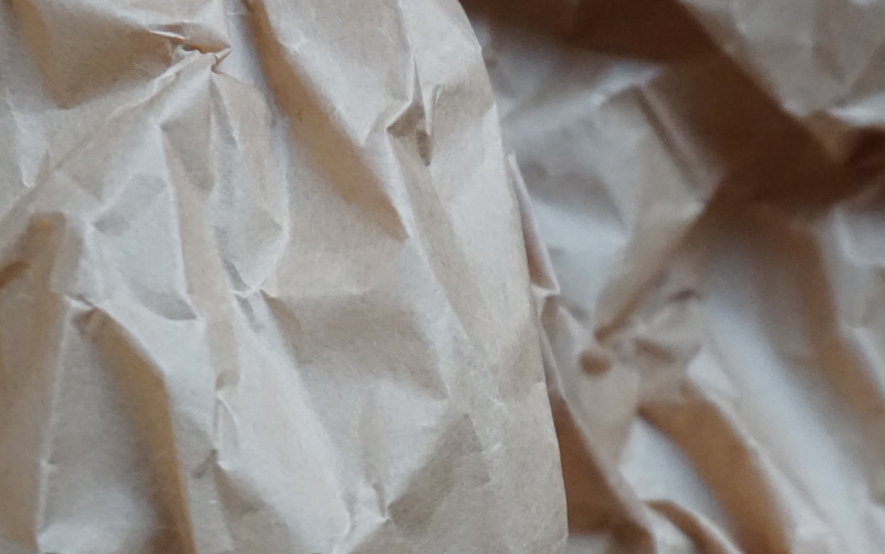
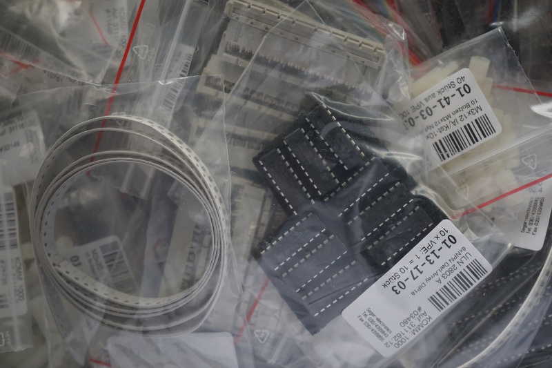
Bags full with electronic parts
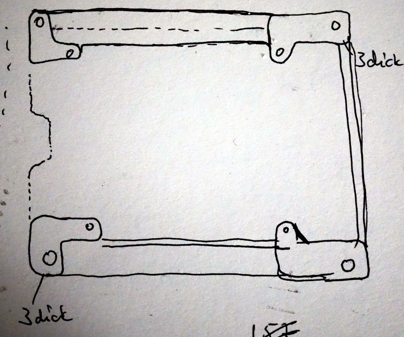
Early design sketch for the pi2 enclosure. This was needed, as the piB should be replaced. Unfortunately, it was almost impossible to get detailed information on how the available boxes can be mounted on a board. This was the reason to make an own design.
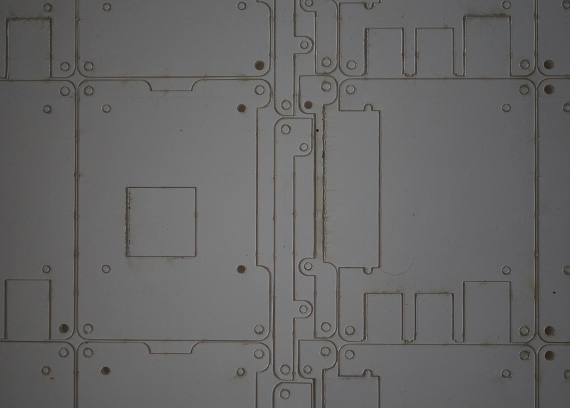
This is how the acrylic glass arrived from the laser cutting service. There is an opaque white cover on the transparent material, a little bit burned on the edges. Nothing from this is seen when cover is peeled off.
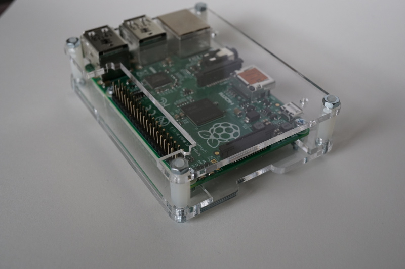
And the assembled encloses. Three 3mm layers, some spacers. And good looking.
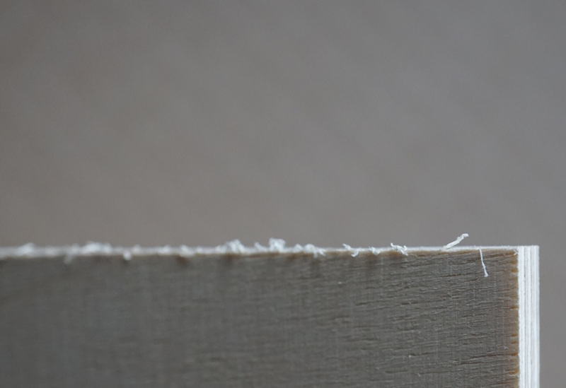
For the base board, plywood is used. The initial state after delivery of the boards clearly shows the need for sanding and some paint.
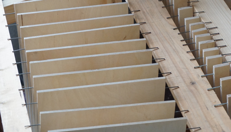
For painting, the boards got nails on both sides to be handled during drying.
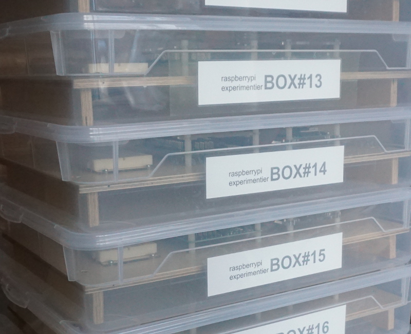
The plastic boxes where the board, pi, electronics are stored (when everything is completed).
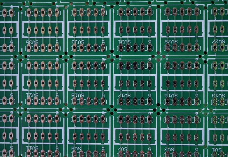
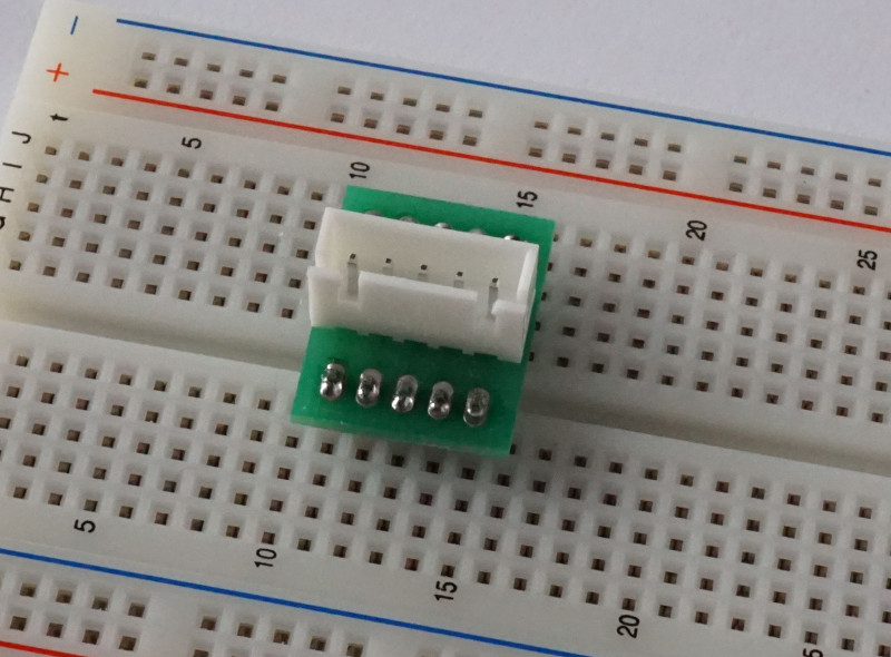
The small adapter boards are together on a larger pcb and need cutting. These are the stepper motor adapters for the breadboard.
Mounting new connector cables from raspberry to adapter board needs 15 new assemblies. For this task, a tool was assembled from some scrap acryl material I found from some recent laser cut orders.
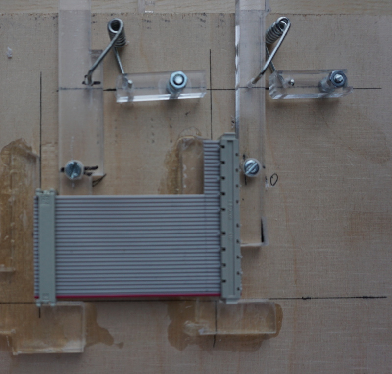
Two brackets position the connectors, and with two levers the connectors are fixed. The springs are from two pegs. The brackets are glued to plywood base with acryl-glue. This allows to assemble the cables in reproduceable quality.
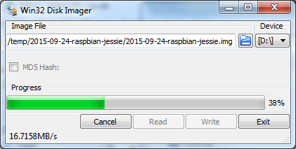
With Win Disk Imager, the SD cards are written. Nice write performance with the new SD cards, almost double the speed of the previous ones used two years ago.
To set up the SD cards, there are ssh connection problems. /etc/ssh/sshd_config needs to be edited to allow root to log in “PermitRootLogin yes”. This made the automatic remote setup procedures run.
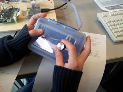
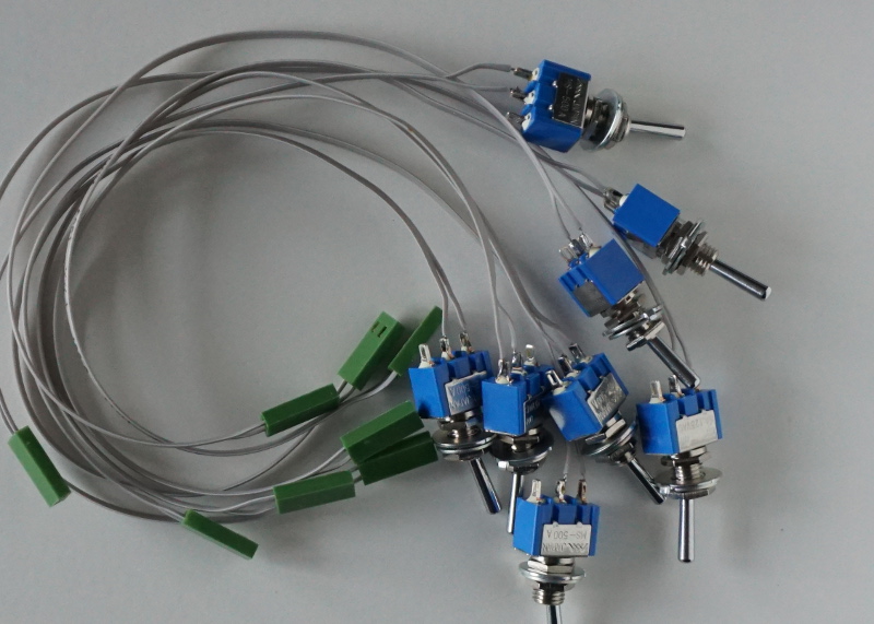
Here some ready to use switches.
And finally (drum fill) the boxes are ready for school.