Monthly Archives: March 2015

Timer for HC-SR04 ultrasonic sensor and scratch

The ultrasonic sensor HC-SR04 is a quite inexpensive ultrasonic sensor, well suited for microcontroller applications.
It produces pulse width modulation directly giving the signal run time.

For 1.7m, at sound speed in air of 340m/s, you get 10ms pulse width.
Up to now, my scratchClient software had no ability to support this device. In order to evaluate different approaches to measure pulse width timings in this range, I have set up an arduino board simulating this device with 10ms timing.
The goal was to have around 1000 measurements and look for the distribution of values.

Approach A was to take python code as found on the net. Two loops, first one looking for raising pulse and second one looking for falling pulse.

python
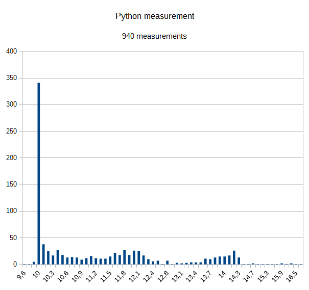
Results are not very precise.
There are quite a lot of measurements at 10ms, but 2/3 of all results are up to 40% higher; few also till 16,5 ms. This is as expected, as the IO system is slow, and a lot of other things are running in the system in parallel.
Advantage is that there are no additional cost, except some voltage dividers needed.

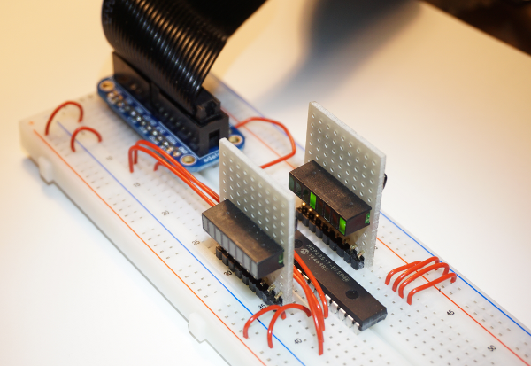
Approach B is a microcontroller subsystem using the atmel 328 chip, sitting on a breadboard and connected with SPI to RPI. The internal oscillator is used for simplicity and reduced cost. This setup is similiar to the adc-setup described in another post.
Time measurement is using the 16 bit timer in 1/64 resolution, yielding 8us values.

ultrasonic_328
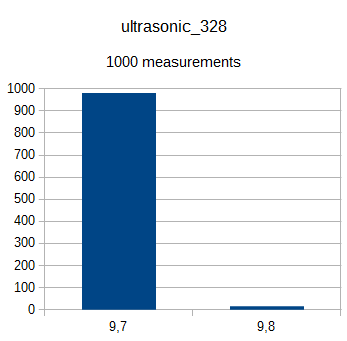
Results are pretty nice, although the deviation is 3% from 10.0ms. Most possible this is caused by the free running oscillator running a little bit too fast; some more investigation is needed here to eliminate software errors.

The code is polling the timer, which is fast enough for this application. SPI is handled with an interrupt coded in assembler. This allows up to 240kHz SPI frequency.
The software is completed and supports up to 4 sonic sensors.
Cost is prox 3.5$ per unit, some soldering and some voltage dividers. No difficult software setup needed.

I found other approaches on the net. DMA code, C-Code or alike. Problem here is the complicated software setup (no ready to use solutions) and the difficult integration into the python environment with RPI.GPIO.

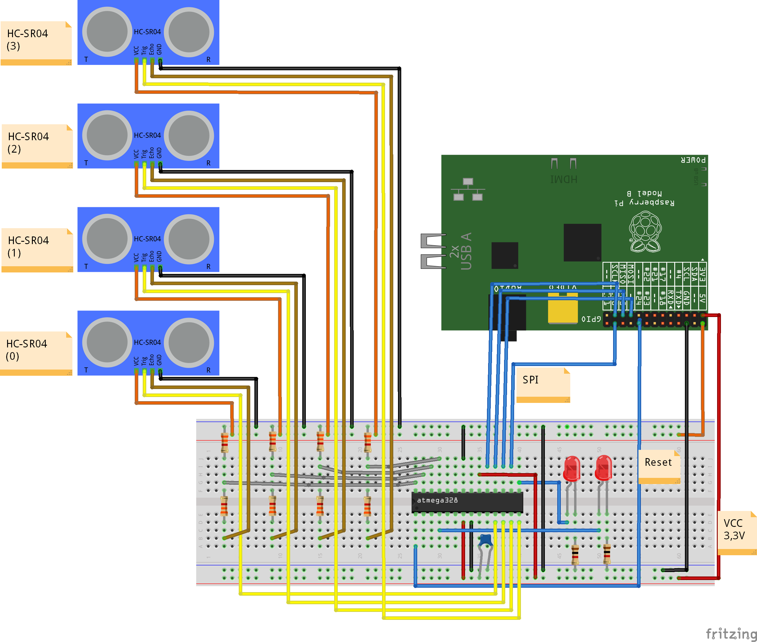
The hardware setup is straightforward. Note the 5V on the supply voltage of the HC-SR04. Doublecheck also the ground connection from HCSR04 to breadboard and to Raspberry. This is important to avoid to get 5V into the raspberry inputs.

For the scratch setup, there is a sample configuration with device(0) connected.

cd ~/scatchClient
sudo python src/scratchClient.py -c config/config_hcsr04_atmel328.xml

In scratch, enable remote sensor connections. You receive ‘distance_A’.

For detailed instructions on how to program the atmel processor, see the documentation in the download file on download page. The programming is performed by the raspberry pi with the SPI cabling.

MCP23S17 aka piFace supported in scratchClient

The 23S17 is the chip used on piFace, It can be used also on a breadboard, providing 16 extra IO-pins for the raspberry.
The adapter adapter.mcp23s17.MCP23S17_Adapter expands the IO-capabilities by 16 ports, either input or output.

 mcp23s17

On the image you see the breadboard setup with the device 23s17, connected with an adafruit breadboard adapter to raspberry pi. The small boards plugged in vertically contain 8 LED with a resistor array. I use those whenever I need more than one LED on a setup.

Programming details

This adapter was a challenge. It needed a configuration specific for each adapter instance of this type, and this complexity was beyond the available <parameter/>-tags. The decision was to break the configuration phase into multiple steps, where after basic creation and setup of the adapter instance the configuration manager passes control to the adapter and provides the local xml config node in this call. The adapter reads the <io/>-tags, configures the necessary adapter methods for sending and receiving variables and gets the device settings for input, output direction and pullup setup.

Configuration details

The device 23s17 allows to have up to 8 devices ‘in parallel’ on one SPI chip select. These devices have hardwired distinct slave addresses. In the configuration, this slave address must be given.

        <parameter name='spi.bus' value='0' />
        <parameter name='spi.device' value='0' />
        <!-- slave address must match the hard wired slave address on the device -->
        <parameter name='23s17.addr' value='0' />

The IO direction for the port pins is defined by <io/>-tags.

        <io id='GPA0' dir='out' />
        <io id='GPA1' dir='out' />
        <io id='GPA2' dir='out' />
        <io id='GPA3' dir='out' />

        <io id='GPA4' dir='out' />
        <io id='GPA5' dir='out' />
        <io id='GPA6' dir='out' />
        <io id='GPA7' dir='out' />

        <io id='GPB0' dir='in' pullup='none'/>
        <io id='GPB1' dir='in' pullup='none'/>
        <io id='GPB2' dir='in' pullup='none'/>
        <io id='GPB3' dir='in' pullup='none'/>
        
        <io id='GPB4' dir='in' pullup='weak'/>
        <io id='GPB5' dir='in' pullup='weak'/>
        <io id='GPB6' dir='in' pullup='weak'/>
        <io id='GPB7' dir='in' pullup='weak'/>

It is generally a good idea to define all of the port pins. Technically it is needed to define those which are used in the application. The id-values are predefined and must be used as seen here.

For ports defined as dir=’out’ outputs, the corresponding adapter input methods can be used:

        <input_value name='inputGPA4'>
            <!-- variable name is the name of the scratch variable which is 
                 send out to the adapter -->
            <variable name='input_4'/>
        </input_value>

For ports defined as dir=’in’ inputs, the corresponding adapter output methods can be used:

        <output_value name='outputGPB2'>
            <sensor name='output_2'/>
        </output_value>

The variables send out from scratch are ‘0’, ‘1’ to set the output pin of the 23s17 to low, high.

The sensor values received from scratch are ‘0’, ‘1’ for the input pin of the 23s17 receiving low, high.

Start scratchClient

scratchClient startup does not need special considerations.

cd ~/scratchClient
sudo python src/scratchClient.py -C config/config_mcp23s17.xml

The file config/config_mcp23s17.xml is an example of a full functional configuration.

Barcode scanner for scratch

barcode

Connecting a barcode scanner to scratch

Some time ago I aquired a barcode scanner, which I use to manage a CD collection based on the EAN-code printed on the packages.

These scanners typically can send codes by emulating HID-class devices. This makes usage from programs quite easy, but you loose input when the program goes to background and other programs get the focus.

Currently I try to bring this code to raspberry pi, using python and pyusb library. This library allows access to usb devices and, very important, can grab devices to be used exclusively by one program. As a side result from this work, I added a barcode scanner adapter to scratchClient.

Install pyusb

Here I found a problem. The usual install did not workwith „pip install pyusb“. This resulted in a ‘backend not found’ exception and „undefined symbol: libusb_strerror“
When I tried to download walac-pyusb-50b1490 from https://github.com/walac/pyusb, this worked, but I had to uninstall the pip-installed code first „sudo pip uninstall pyusb“.

The needed backend packages are already available in raspbian, you can check this with

apt-cache pkgnames | grep libusb

You should find libusb-1.0-0 in the list.

Setup Scanner for USB and CR-suffix

A few preparations are needed with the scanner to enable HID mode. With my scanner I got a handbook with a huge amount of programming codes. You start programming with a ‘start programming’ code, scan the appropriate setup code and exit programming with an ‘end programming’ code.

For my sample, I have setup HID mode, and added exit code/suffix CR. This is needed to detect complete sequences. The adapter in scratchClient relies on this.

Configure idVendor and idProduct

Another preparation is the configuration of idVendor and idProduct in the adapter’s config file. Use the utility enum.py to list the devices available

cd ~/scratchClient
python tools/usb/enum.py

Here the output for my scanner

DEVICE ID 0c2e:0200 on Bus 001 Address 007 =================
bLength : 0x12 (18 bytes)
bDescriptorType : 0x1 Device
bcdUSB : 0x110 USB 1.1
bDeviceClass : 0x0 Specified at interface
bDeviceSubClass : 0x0
bDeviceProtocol : 0x0
bMaxPacketSize0 : 0x8 (8 bytes)
idVendor : 0x0c2e
idProduct : 0x0200
bcdDevice : 0x5881 Device 88.81
iManufacturer : 0x1 Honeywell Scanning and Mobility
iProduct : 0x2 Honeywell Scanning and Mobility Scanner
iSerialNumber : 0x0
bNumConfigurations : 0x1
CONFIGURATION 1: 300 mA==================================
bLength : 0x9 (9 bytes)
bDescriptorType : 0x2 Configuration
wTotalLength : 0x22 (34 bytes)
bNumInterfaces : 0x1
bConfigurationValue : 0x1
iConfiguration : 0x3 HID Keyboard
bmAttributes : 0x80 Bus Powered
bMaxPower : 0x96 (300 mA)
INTERFACE 0: Human Interface Device ====================
bLength : 0x9 (9 bytes)
bDescriptorType : 0x4 Interface
bInterfaceNumber : 0x0
bAlternateSetting : 0x0
bNumEndpoints : 0x1
bInterfaceClass : 0x3 Human Interface Device
bInterfaceSubClass : 0x1
bInterfaceProtocol : 0x1
iInterface : 0x0
ENDPOINT 0x81: Interrupt IN ==========================
bLength : 0x7 (7 bytes)
bDescriptorType : 0x5 Endpoint
bEndpointAddress : 0x81 IN
bmAttributes : 0x3 Interrupt
wMaxPacketSize : 0x8 (8 bytes)
bInterval : 0xa

What you also should check is the iConfiguration to be a HID Keyboard.

For verification open a text editor like leafpad: when scanning a code, this should be entered into the editor as a text string.

Edit config/config_barcode.xml and adjust the vendor/product id there.

In my environment, I use a powered USB hub to connect the scanner.

Start scratchClient

cd ~/scratchClient
sudo python src/scratchClient.py -c config_barcode

The file config/config_barcode.xml is a starting point for a project. Add other adapters as needed.
When scanning barcodes, these are send to scratch. Do not forget to enable remote sensor connections.

scratch_barcode