Category Archives: sensor

scratch 1.4 mesh network with scratchClient

Scratch 1.4 on raspberry pi allows to connect with other scratch instances on other computers.

This is an experimental feature. This feature is not available in scratch1.4 for linux or windows, not in scratch2.

With this feature multiple scratch 1.4 can share events and (global) variables.

As this feature is experimental, there are some constraints and problems especially when scratchClient is used also.

ScratchClient has a feature to interconnect computers too. This uses scratchCommunicationServer.py which allows filtering and segmentation of larger networks.

Enable Mesh Session

Scratch 1.4 has a ‚Share‘ menu point. This menu has different content when ‚shift‘ is pressed before the mouse click.

Enable mesh session by ‘shift’ and press ‘Share’-menu.

‚Host Mesh‘ means that this scratch is opening the mesh. It ‚hosts‘ the mesh. In other words this scratch becomes a server.

‚Join Mesh‘ means that the scratch connects to a mesh network another computer has opened before. In other words this is a ‚client‘. The client needs to know the IP address of the server.

When ‚Host Mesh‘ is executed, the IP address of the computer is displayed.

There is a menu entry on a ‚host‘ computer which allows to display this again:

Computer A:

enable ‘host mesh’ session
display ip address, e.g. 192.168.2.200

Computer B:

join mesh session
enter ip address of computer A

Broadcast events of one computer are sent to computer B also.

Global variables of one computer are visible on ‘sensing’ tab, sensor values on the other computer.

The variable (here ‚a‘) can only be changed on the one computer where it is is created. Sensor value can‘t be changed.

Best Practice

  • Scope: Variables should be ‘for this sprite only’ whenever possible. Use ‘for all sprites’ only if needed or when these should be transferred to other computer.
  • Naming: Variables and events which need to be transferred should get a special name which includes the sending computer name. So if sending computer is ‘box07’ and variable is ‘a’, then name is ‘box07.name’.

Problems, Constraints

Persist connection

The client side does not store it’s state in the project file. ‘join mesh’ needs to be done each time the project is opened.

Topology with scratchClient

scratchClient connection works on server side only. On client side, when sensor network is enabled then the mesh connection is stopped and thus scratchClient can’t be used.

The ‚enable remote sensor connections‘ command is not needed when ‚Host Mesh‘ is used.

Warning

ScratchClient issues a warning about an unknown command, but this does not stop anything.

Infrastructure

The involved computers need to be connected to a network.

When computers are configured to use fixed IP-Addresses, then for a two computer network a crossover-ethernet patch cable can be used.

Network connection on a raspberry pi.

The color of a cable does not imply whether a normal connection or crossover connection type cable is used.

scratch2 connected to scratchClient

Did you ever want to control GPIO from scratch2 ? Or other sensors connected to a raspberry pi ?

The last days I worked on connecting scratch2 with GPIO on raspberry and more.
To be precise, this is done by either using scratchx or since june 2017 with the standalone version of scratch2 for raspbian.

  • use scratch2 version named scratchX which supports ‘scratch extensions’. This version is identical to scratch2 with few limitations. Or use the standalone version on raspberry.
  • extending scratchClient to talk with scratch2 and providing sensor values and events, but also receive values from scratch2 and events.
  • scratchClient using adapters to connect peripheral devices as usual. For example to GPIO.
  • The blocks in scratchX are defined from the information available in the config file used by scratchClient.

This new version of scratchClient is still supporting scratch1.4 and there are no changes in the config files needed.

One of the limitations in scratchX are that sharing projects is not possible.

The extension blocks in scratchX are defined using the definitions from the config xml file from scratchClient. So there is no programming effort needed to build the extension file.

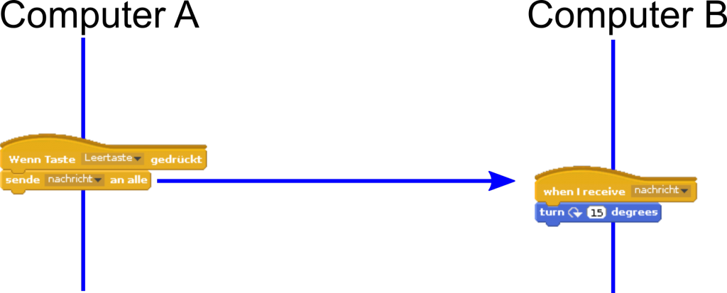
Current implementation allows to send/receive values and events from scratchX to/from scratchClient. This is similiar to the features available in scratch1.4 with the broadcast system.

Problems, Inconsistencies with scratch 1.4 broadcast system

In legacy 1.4 scratch, there are some predefined blocks for motors and sensor names for scratchBoard. This needed many explanations for unexperienced users to avoid confusion.

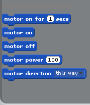
scratch 1.4 motor blocks in sensing palette

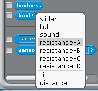
scratch 1.4 default sensor names

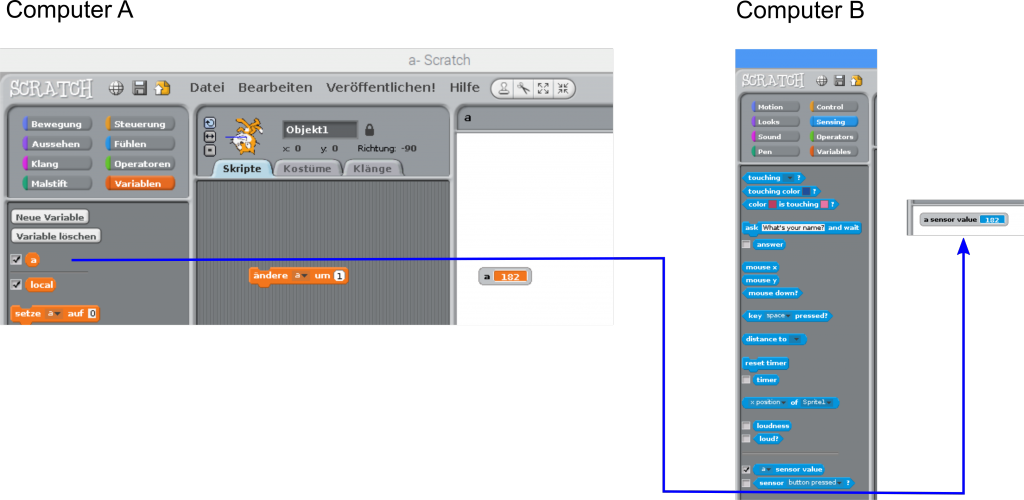
It was also difficult to explain that values from scratchClient are received as sensor values, but values to be sent out need to be defined as variables ‘for all sprites’.

In addition to this, the extra step ‘enable remote sensor connections’ is hidden down in a context menu of a block on lower edge of the window.

Advantages of the scratch2, scratchX block based interfacing

In scratchX, all the capabilities of the external system are exposed as blocks. This avoids all the mentioned problems from legacy scratch 1.4.

Modifications in scratchClient

scratchClient in its initial design is scratch1.4 centric. The start and stop logic is scratch 1.4 oriented and needed another structure.

During this work, the internal web app was lifted to use tornado framework. Which has build in websocket support and is easier to use as cherrypy. As scratchX is online only, the connection to a local data provider needs to bypass the ‘same server policy’ and this was quite simple to achieve with tornado.
Monitoring and simulation of events is still possible by using the internal web server. Some bugs have been removed in the web pages on this way.

Setup procedure

As the experimantal scratchClient is merged into scratchclient, the installation is same as for scratchClient.

Start scratchClient with the configuration xml file for your hardware. I recommend using python3 to run scratchClient. Unicode support is the reason for this.

Context

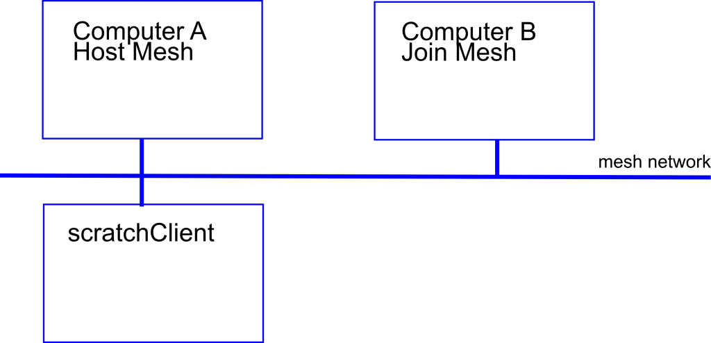
scratch2 / scratchX does not need to run on same computer as scratchClient. The communication beween scratchX and scratchClient uses websocket and http requests. In my test environment, scratchX runs on windows and scratchClient either on a raspberry or on windows.

Start scratchX

Load http://scratchx.org/#scratch into the browser.

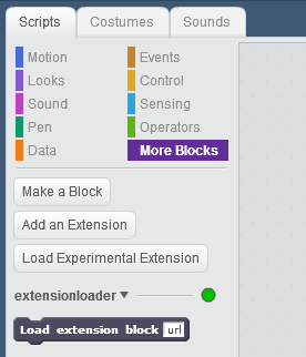
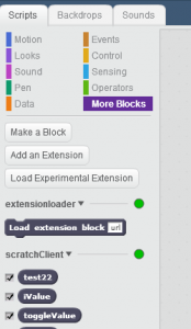
Load extension loader

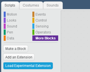
In ‘more blocks’, ‘Load Experimental Extension’,

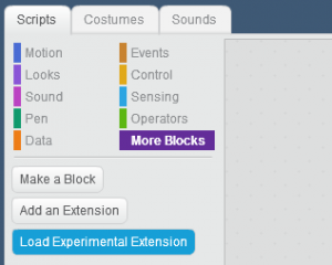
press on Load Experimental Extensions and open Extension URL

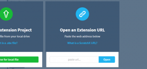
Paste the following url into the form

https://megjlow.github.io/extensionloader.js

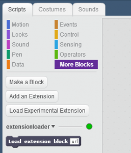
This url brings the Load Extension Block into the additional block palette.

Connect to scratchClient

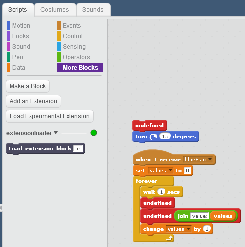
The Load Extension Block is now used to load the scratchClient configuration. Best practice is to prepare a small script in stage which loads the scratchClient config.

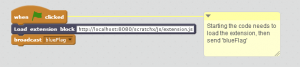
Add a wait block before the ‘broadcast [blueFlag]’ with 5 seconds. This gives the extension the needed time to load and to initialize.

The program should use ‘blueFlag’ in all places where the green flag hat  is usually used.

The url to use to load the scratchClient extension is

http://localhost:8080/scratchx/js/extension.js

Copy paste this url into the ‘load extension block’. If scratchClient is running on a different computer, change ‘localhost’ to either the other computer’s IP-address which is something like 192.168.2.203 or perhaps a more meaningful name if the network configuration allows.
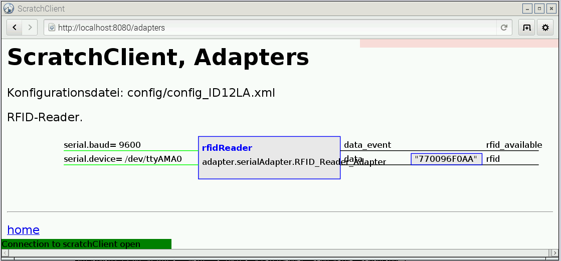
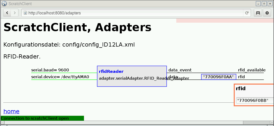
Validation

See the ‘green’ dots to the right of the extension name. If these turn red, connection is lost. Possibly scratchClient has been stopped, can’t be reached or other problems. In my tests the connection was stable.

Extra step for the preview: start legacy scratch and open remote sensor connection.

Loading a project using scratchClient extension

A program loaded from file system shows the Load Extension Block, but not the scratchClient extension. The blocks from the scratchClient extension are displayed as red blocks.

When program is started with green flag and the proposed initial script is executed, the Load Extension Block reads the extension from scratchClient and the program can be used.

Start scratch2 on raspbian

In raspbian jessie june-2017, there is a standalone scratch2 version available.

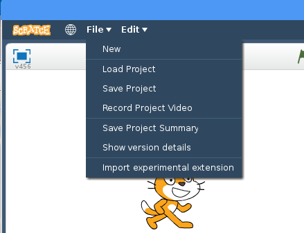
Start from programming/scratch2.

Press shift key and the file menu. The file menu now displays more options.

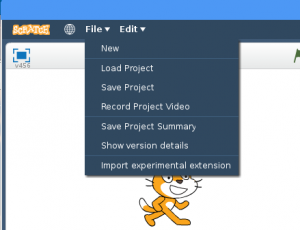
Select import experimental extension.

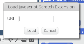
Paste the url into the dialog: http://localhost:8080/scratchx/js/extension.js

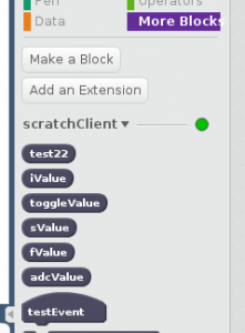
Validate in ‘more blocks’. The example here is for a test adapter and looks different for your configuration file.

This scratchClient version is released

There are no known limitations for this release.
Just start scratchClient and use either scratch1.4 (enable remote sensor connections) or follow the procedure to set up a scratch2/ scratchX connection.

Some features have been removed. Command line switches to control the gui are removed. As the web app server is needed to connect to scratchX, this does not allow to disable the web browser.

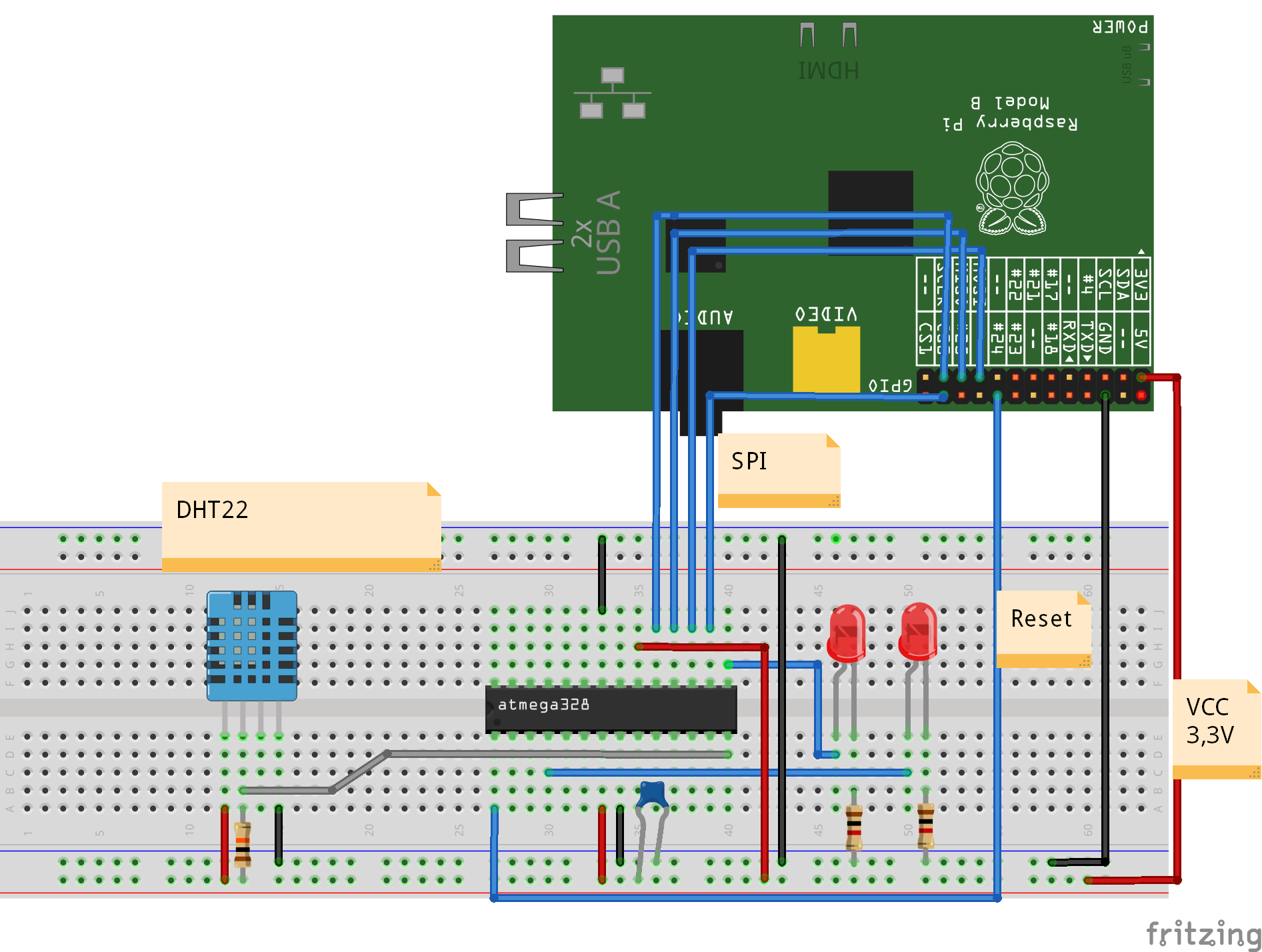
Example: Controlling two wheel robot pi2go with scratch2

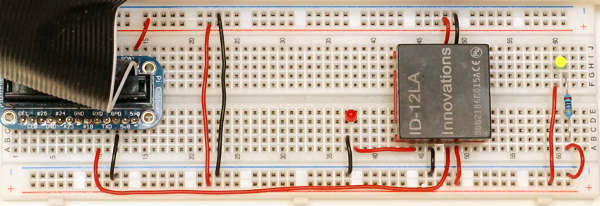
The tests for the scratchX integration have been performed with a new pi2go-configuration. This includes GPIO, PWM, hardware PWM and ADC chips.

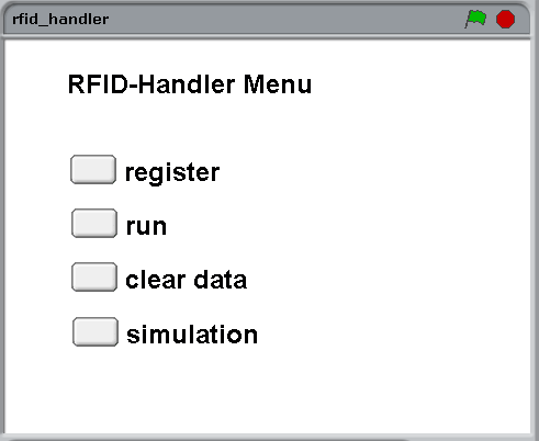
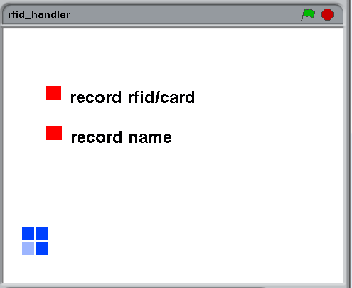
The monitoring/simulation web page display the many inputs and outputs available for this robot.

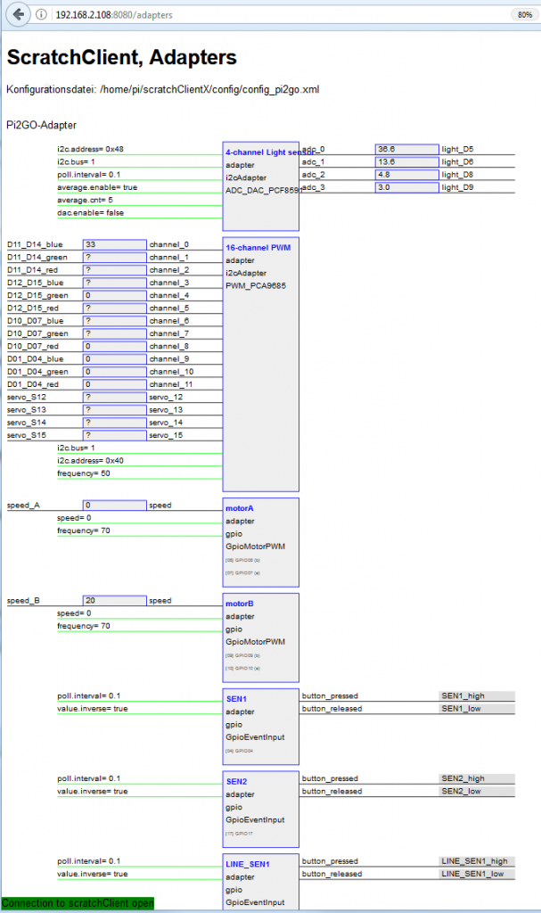
Not all adapters fit on the page.

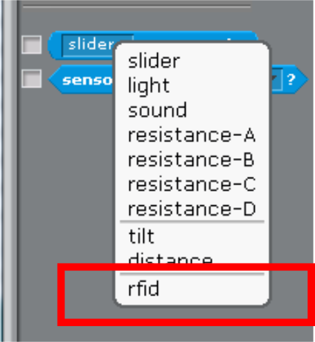
The blocks build from this config in scratchX are (not all blocks shown).

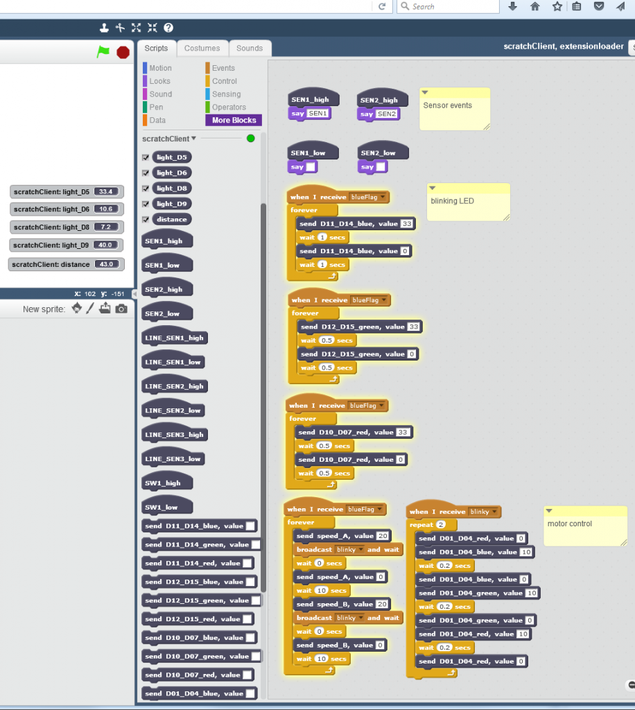
On stage, there are the lights reporters and distance reporter visible.


Sense Hat, Astro Pi connected to scratch

Sense Hat (announcement by raspbery pi foundation) is an add on board for PI2, which supports environmental sensors for temperature, pressure and humidity. There is an IMU-sensor included. And a fancy 8×8 RGB-LED matrix. And a small joystick which provides cursor keys and the enter key for the center button.

The software to drive this board is wrapped in a python API. This APi is handy to be used for scratchClient and connect it to scratch.

The adapter is adapter.senseHat_adapter.SenseHat_Adapter.

LED Matrix

Events are ‘clear’, setPixel_xy’ and ‘clearPixel_xy’.

‘clear’ is pretty straightforward and clears the matrix to blank.

The pixel operations need variables to be set before the setPixel can be performed.

procedureCall
x and y position needs to be set and the color needed. The event sense_led_xy_on is mapped to setPixel_xy by scratchClient. This mapping is done in the configuration for this adapter (scratchClient/scratch/senseHat/config_senseHat.xml).

        <input name= 'clear'>
            <broadcast name='sense_led_clear'/>
        </input>
        
        <input name= 'setPixel_xy'>
            <broadcast name='sense_led_xy_on'/>
        </input>
        
        <input name= 'clearPixel_xy'>
            <broadcast name='sense_led_xy_off'/>
        </input>

The commands available in scratch are the <broadcast/> elements. These all have the prefix ‘sense_’.

Color supports basic colors in plain english (red, green, white, blue, and some more) and ‘#aabbcc’ which is hex notation in red, green blue. In the  scratchClient documentation are the details, look for the ‘colorType’-definition in chapter ‘Adapter Data Types’ .

In my experiments, I found that small rgb-values for the LED, e.g. #030303, which is red=3, green=3, blue=3 are not displayed, but leave the LED dark. Obviously the API is doing some gamma correction and discards small values. Try higher values if you run into this problem. #303030 seem to be smallest values available.

For the clearPixel call, no color needs to be set.

There is a scratch sample application scratchClient/scratch/senseHat/sense_hat_led.sb which allows to set/clear pixel in a (hopefully) intuitive way. Move the blue cursor mark with cursor keys and toggle the LED by blank key.

led_control

Stage printout

The joystick on senseHat can be used to move the cursor around. Unfortunately the center button sends ‘enter’, which is the ‘green flag event’ in scratch and restarts the code. Thus the toggle LED is mapped to the blank bar on keyboard for this sample.

led-matrix

A LED pattern, camera shutter time 1/60 sec

led-matrix-2

Same LED pattern, camera shutter time 1/100 sec displaying only part of the LED

Took me  a while to identify the problem in the second photo: the exposure time was 1/100 sec, so the refresh rate of 80Hz for the LED produces fake ‘missing LED’ on the sense hat.

Environmental Sensors

The humidity, pressure and temperature values are sent at a limited frequency to scratch. And only when values change. For this adapter, the precision of values sent is limited to one decimal digit. This reduces communication effort and system load by 10 percent.

The temperature value and dependent from this the humidity sensor suffers from heating of the hat board by the primary processor. On my desktop, the temperatures reported have been prox 10 degree too high. There are reports of people who separated the Pi and hat by a ribbon cable and got better results.

IMU Sensor

The gyro, accel and compass sensor contribute to the orientation signals, which are sent as orientation_yaw, orientation_roll and orientation_pitch to scratch. These values are quite stable. These values also are sent only at a limited frequency and reduced precision to one digit number. But 1/10 degree is good for most purposes.

Installation of prerequisite software

The board needs software to be installed. See the installation instructions on the API side

Start scratchClient

cd ~/scratchClient
sudo python src/scratchClient.py -c scratch/senseHat/config_senseHat.xml

RFID Tag Reader

There are nice little tag reader devices available from ‘innovations’ as the ID-12LA. It works with the 125kHz cards or tags, does not need an external antenna and can work directly with Raspberry Pi. I recently got one on my desk and connected it to scratch.

For the setup, there is the possibility to connect it directly to Raspberry Pi serial port, or to buy an usb-adapter. I have choosen the simple way, but as the pin spacing is 2mm there is a breakout board needed to match a breadboard. I used some 2mm spaced sockets on the adapters and have the module pluggable.

The two images show the breakout board without the modue and with the module. The yellow LED at the right is a ‘always on light’ used as a power indicator. Quite useful to see if a breadboard is connected.

rfid-setup_0

rfid-setup

For the connection to scratch a special adapter is needed for scratchClient. The adapter.serialAdapter.RFID_Reader_Adapter opens the serial port and extracts the Tag-Numbers from the byte stream. When data are available, these are sent to scratch. Then a broadcast event is published ‘rfid_available’. A sample config file is provided config/config_ID12LA.xml.

ScratchClient start is performed by

sudo python src/scratchClient.py -c config/config_ID12LA.xml

Start scratch 1.4, open ‘remote sensor connections’. When a tag or card is near the reader, then scratch should receive a variable ‘rfid’ containing a 10 bytes hex number.
sensor2

A sample program can record tags and associated names in an internal ‘database’, build from two lists. One list is for names, the other for rfid.

rfid_handler_menu

select ‘register’ to read in tags and names (from keyboard).

rfid_handler_record

In ‘run’-screen, tags scanned are checked against the available rfid in rfids-list. When match exist, the cat tells the name found.

rfid_handler_run

The green/blue boxes are an indicator for read events. For each event, it should turn clockwise.

The ‘clear data’-Button clears internal data.

And for all the impatient people there is a simulation mode which populates the database with some dummy values. In run mode, the simulation displays a ‘random’-button which simulates input.

scratchClient can also be used to provide input to scratch. Open http://localhost:8080 and navigate to ‘adapters’.

scratchClient_adapters

on the right hand side, there is lat value for rfid shown. The Quotes are mandatory here, as scratch needs to interpret values as strings. Click into the text field, you get an entry popup.

scratchClient_adapters_entry

Confirm the entry by ‘enter’. Then click on the rfid_available- string and a red blink rectangle confirms the event is sent to scratch.

The formatting of the class name in the adapter box is not perfect, will change this if there is some spare time.

One feature in the scratch code is how the simulation data insertion is solved. It is not possible to overwrite sensor values. So when sensor values arrive, the data are copied to a global variable and a new broadcast is issued.

In the stage scripts, the input from the sensor is copied to a globale variable.

script

All code processing rfid data is based on ‘rfidValue’ and ‘rfid_for_processing’.

In the rButton-script, this global variable and event is produced.random

Downloads

scratchClient

scratch sample program

Atmel328 firmware for DHT22 Temperature, Humidity

The temperature, humidity sensor DHT22 is a quite inexpensive sensor, well suited for microcontroller applications. It uses same protocol as DHT11.
It is connected by a single wire, needs 5ms for a read cycle, but a quite challenging protocol where the pulse width gives ‘0’ or ‘1’ bit values.

This is a typical application for a coprocessor for raspberrypi. For an atmel328, it is not a challenge to handle this protocol.

atmel_dht22_Steckplatine

The signal from this sensor is relying on exact timing.

dht22_waveform

The initial ‘pulse low’ is not in the chart.

The firmware uses internal timer with 1 us resolution to measure pulse widths. Using the timer unit makes this method insensitive when interrupts produced by SPI communication occur in parallel.

The atmel firmware triggers the data aquisition, and provides a 40bit ‘raw’ result to the raspberry pi host computer. The conversion of the values  to temperature, humidity values is performed in python code. See the sample code provided in the download to see this procedure.

Of course, there is an adapter for scratch.
cd ~/scratchClient
sudo python src/scratchClient.py -c config/config_dht22_atmel328.xml

A detailed description on how to program the firmware is on the download page.