Having some spare time in the scratch course at school, we did a short ‘computer art project’.
A short introduction to the topic was presented, some materials taken from the following web pages:
– https://gigers.com/blog/computerkunst-mit-snap-wiederholung-und-zufall/
– https://monoskop.org/images/2/25/- Reichardt_Jasia_ed_Cybernetic_Serendipidity_The_Computer_and_the_Arts.pdf
– http://joachim-wedekind.de/Downloads/AtlasComputerkunst_redsize.pdf
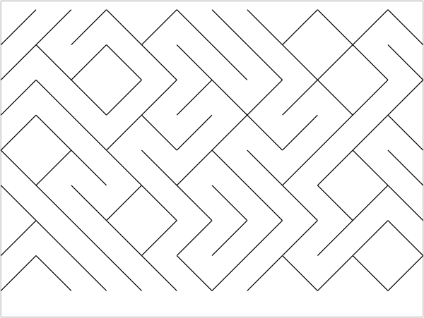
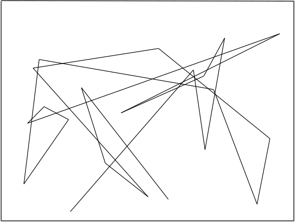
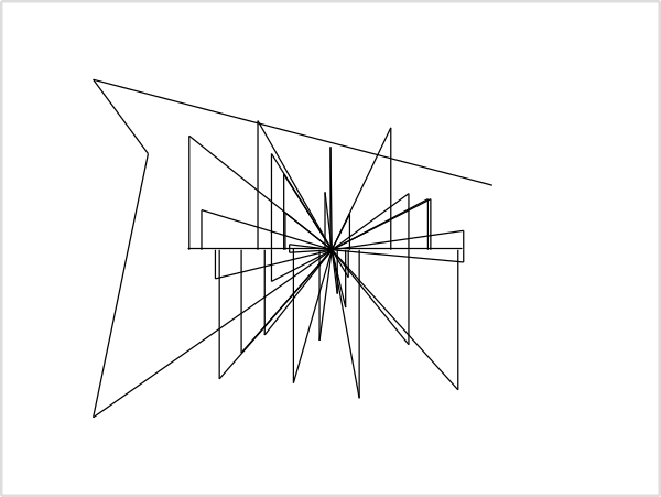
The task for the kids, 7th class, was to use simple geometrical patterns combined with some randomness.
Using scratchClient, a pen plotter axidraw SE/A3 was connected for the class room. A standard laptop was used for a plotter server, caching the kids graphics and spooling to the hardware.
Kids worked on RPi4 boards, scratch3 local and sccratchClient (for scratch3) as a backend.
Results 2024
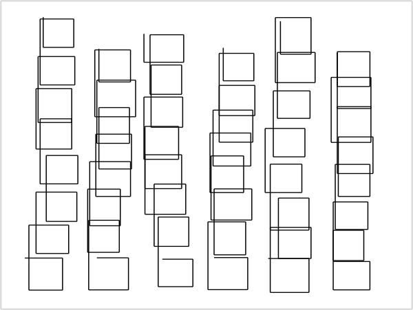
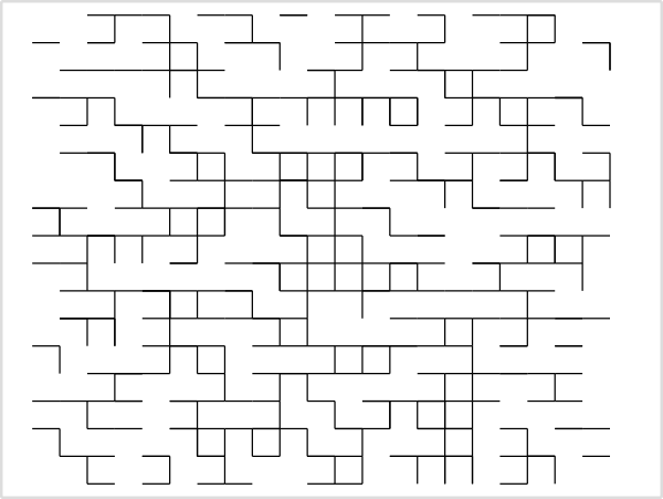
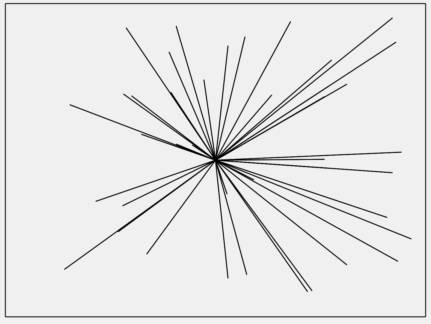
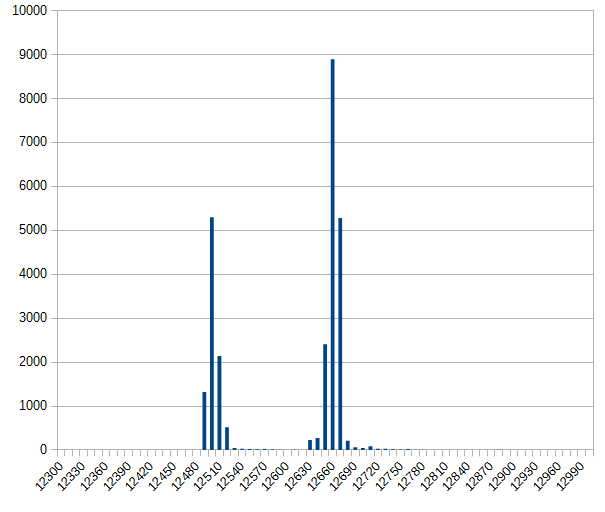
The kids hat a lot of fun working on this project. Within 90 minutes, there have been about 500 images produced (a lot of them just to see how ‘randomness works’), a total of about 420.000 graphical commands.
Some results produced have been plotted. The images presented here have been converted from the scratch graphical commands to svg images, then to pixel graphics.
The images are published with a copyright to the school.
Results 2025
Video showing results.
In the 2025 course, the kids mainly started with a CAD approach: an image design was implemented using Scratch. It was only in the second lesson that they worked with random modifications of graphic elements.
The plotter software records all designs from the workstations. This makes it possible to show the development of ideas. The video shows excerpts of such evolutions.
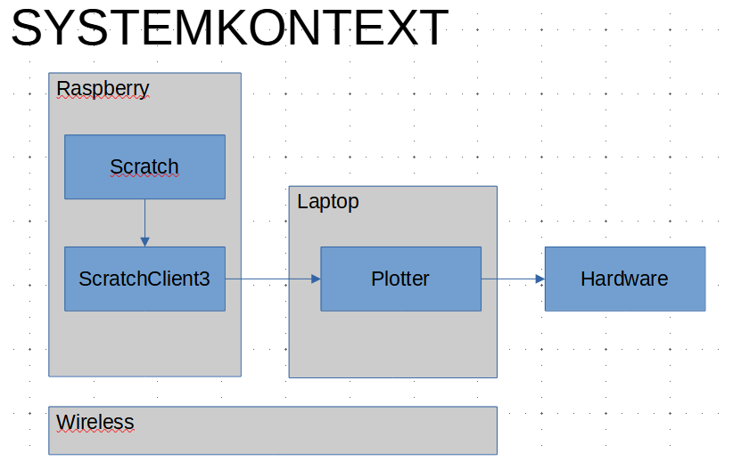
System Context
The system fortunately worked pretty good. The scratchClient for the plotter used UDP broadcast to find a plotter server on a laptop. ScratchClient then used a ‘plotter’ adapter so send commands to plotter server.
The plotter server software then caches the results of the eight groups in the course. For the hardware axidraw, the plotterServer scales the output and does some drawing optimizations like reducing redundant pen lift up, down operations.
For the scratch project, a sample project was provided which demonstrated the ‘how it works’. From this, the kids developed their own idea.
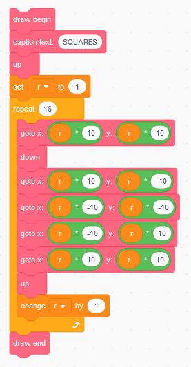
Basic plotter commands are
- begin, end: The wrapper for the plotter Server to separate images
- up, down: pen move commands
- goto_x_y x=, y= : absolute move
- change_x, x=: change x position
- change_y, y=: change y position.
All commands updated local stage and simultaneously have been sent to plotter server.
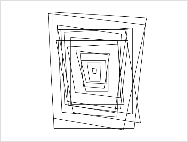
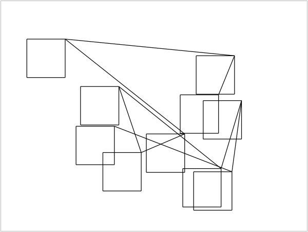
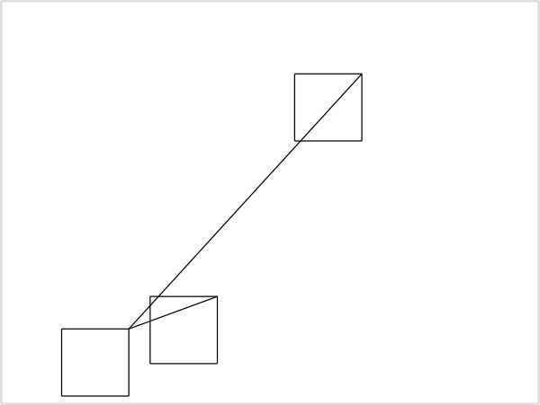
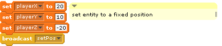
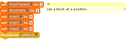
Here a sample scratch snippets to draw some nested squares:
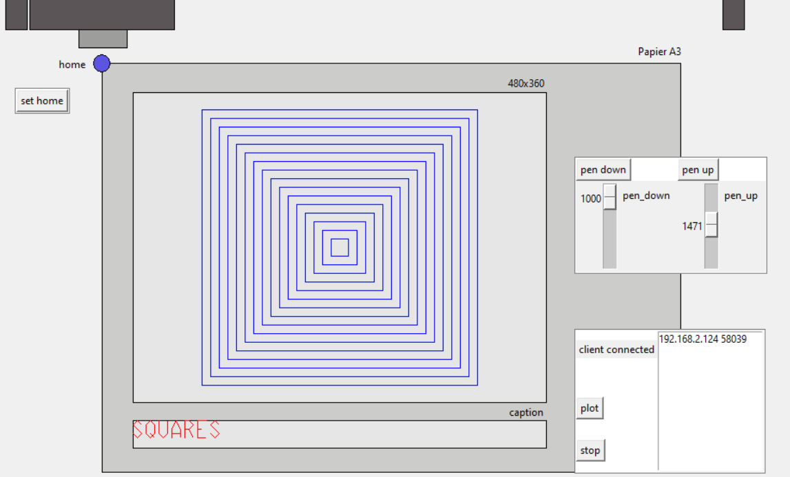
The related output on the plotter server is showing the canvas printed aka the stage visible on the scratch workstations. Some adjustment knobs for pen lifting are needed.
