Monthly Archives: February 2014

ADS1015 als AD-Wandler am Raspberry Pi

Siehe auch
Atmel 328-Prozessor als AD-Wandler für Raspberry Pi
MCP3202-AD Wandler am Raspberry PI
Arduino UNO, NANO connected to Scratch

Die Firma adafruit vertreibt eine kleine Platine, die einen 12-Bit ADC ADS1015 enthält. Dieser hat eine eigene Referenzspannung und einen einstellbaren Verstärker. Bis zu 4 Analogkanäle können angeschlossen werden. Der nutzbare Spannungsbereich ist 0 bis 3.3V, da im Beispiel die Platine mit 3,3V betrieben wird.

Diese Platine kann zum Anschluss von analogen Sensoren mit scratch benutzt werden.

Benötigt: Steckbrett, Lötkolben, Lötzinn, Steckkabel Buchse/Stecker und einige kurze Drahtstücke. Potentiometer 2.2kOhm (hier geht auch bis 10kOhm) als Beispiel für einen Sensor.

aufbau
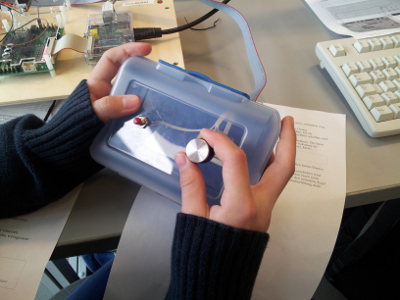
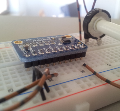
Um die Platine an den RPi anzuschliessen ist ein Steckbrett nötig. Die Platine wird ohne montierte Steckleiste ausgeliefert, diese muss selber angelötet werden. So sieht das dann aus.


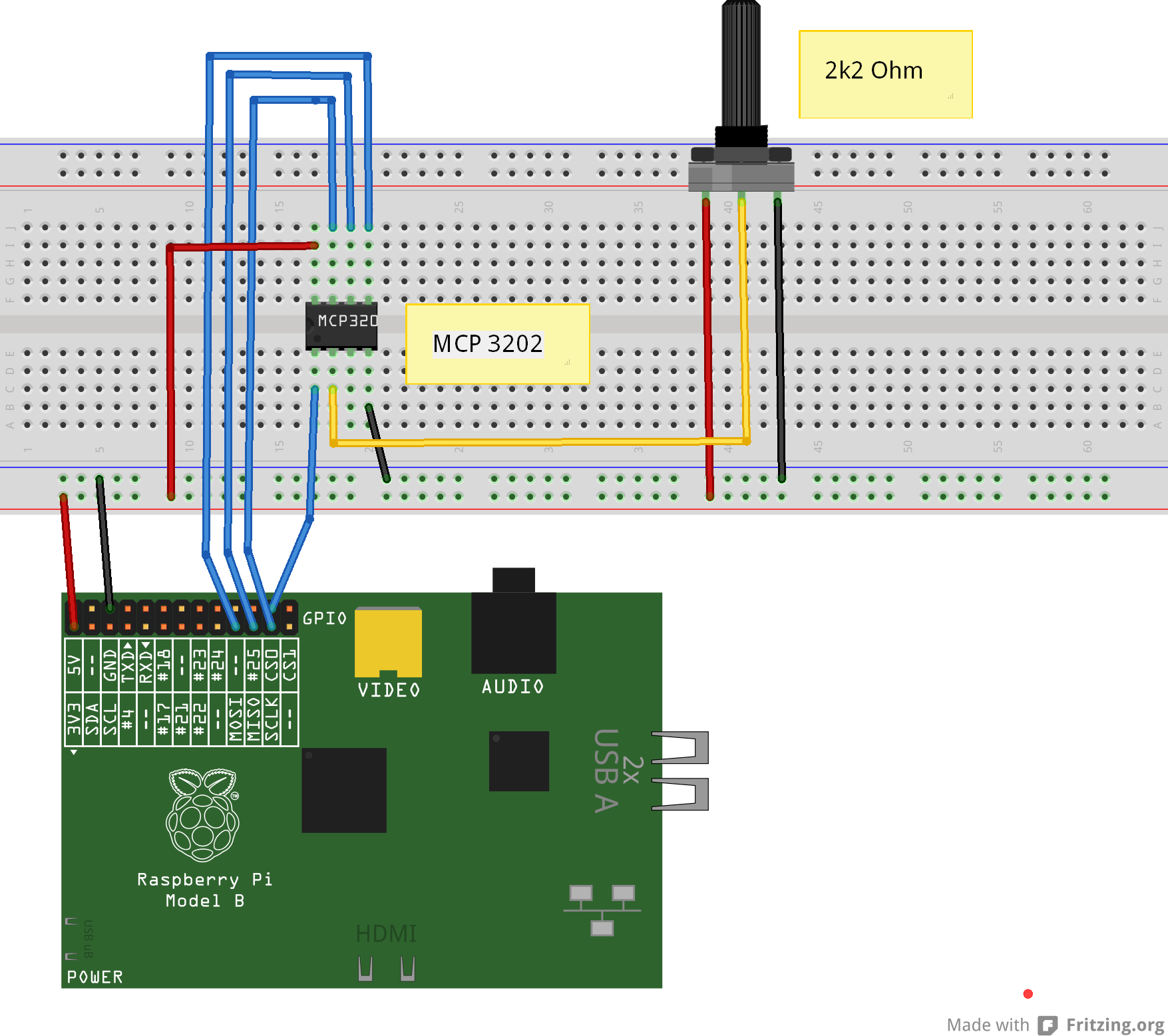
Die Verkabelung ist hier aufgezeichnet.

ads1015_bb

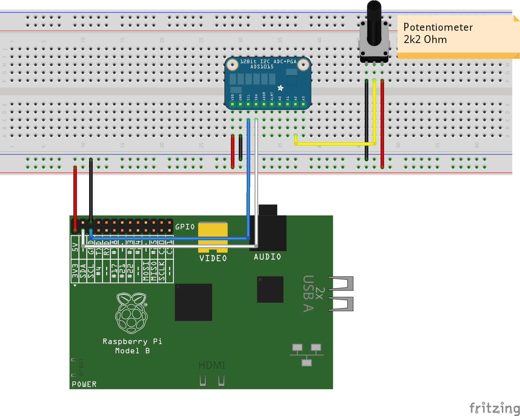
Hier ist das Potentiometer an den Eingang A2 angeschlossen. Es kann jeder Eingang verwendet werden, das muss dann aber auch in der Konfiguration des scratchClient berücksichtigt werden.

Vorbereitung (siehe auch die Installationsanweiung in der Dokumentation des scratchClient):

sudo apt-get python-smbus i2c-tools
sudo modprobe i2c-bcm2708
sudo modprobe i2c-dev

Die ‘i2c-tools’ sind eine Sammlung von Werkzeugen, um den i2c-Bus zu prüfen und Geräte anzusprechen. Nach der Verkabelung kann geprüft werden, ob der Baustein ansprechbar ist.

pi@raspberrypi ~ $ sudo i2cdetect 1
WARNING! This program can confuse your I2C bus, cause data loss and worse!
I will probe file /dev/i2c-1.
I will probe address range 0x03-0x77.
Continue? [Y/n] Y
     0  1  2  3  4  5  6  7  8  9  a  b  c  d  e  f
00:          -- -- -- -- -- -- -- -- -- -- -- -- --
10: -- -- -- -- -- -- -- -- -- -- -- -- -- -- -- --
20: -- -- -- -- -- -- -- -- -- -- -- -- -- -- -- --
30: -- -- -- -- -- -- -- -- -- -- -- -- -- -- -- --
40: -- -- -- -- -- -- -- -- 48 -- -- -- -- -- -- --
50: -- -- -- -- -- -- -- -- -- -- -- -- -- -- -- --
60: -- -- -- -- -- -- -- -- -- -- -- -- -- -- -- --
70: -- -- -- -- -- -- -- --
pi@raspberrypi ~ $

Der ADS1015 taucht hier mit der (hexadezimalen) Adresse 0x48 im Listing auf.

Start des scratchClient:

cd ~/scratchClient
sudo python src/scratchClient.py -c config/config_adc_ads1015.xml

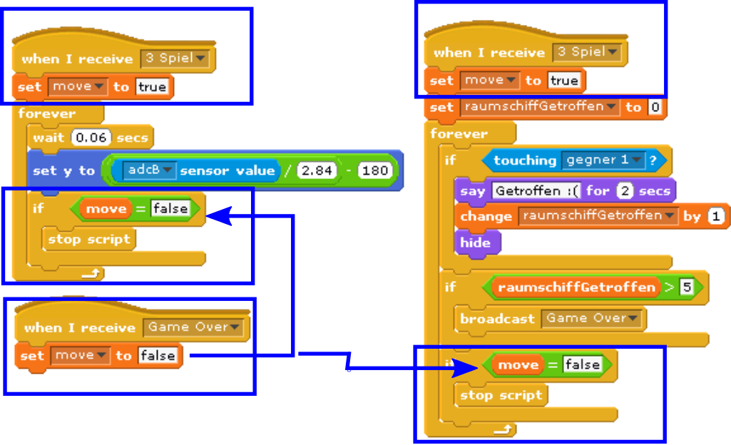
Scratch erhält die Werte vom scratchClient  im Bereich 0..3300 (ungefähr) als adc_A2. Das ungefähr deswegen, da der Baustein die Spannung absolut mit seiner eingebauten Referenzspannung misst. Wenn jetzt die 3.3-V-Versorgung der RPi etwas vom Sollwert 3300 mV abweicht, so weicht auch der Maximalwert ab.

Der Name ‘adc_A2’ ist in der Konfigurationsdatei so eingestellt, da im Beispiel der Kanal A2 verwendet wird.

Spielekonsole Brotbox

konsole_in_action

Die Spielekonsolen konnten im Kurs nicht gebaut werden. Um trotzdem die Spiele steuern zu können wurden einfache ‘Standard-Konsolen’ bereitgestellt. Das Bild zeigt ein Beispiel: Brotdose aus dem Supermarkt und ein Potentiometer und ein Taster eingebaut.  Die Anbindung an der Adapterplatine erfolgt mit etwa 60 cm langem Flachbandkabel,

Andere Konsolen haben vier Taster oder zwei Potentiometer und einen Taster.

Eine Variante ist ein Brett mit zwei IR-Abstandsensoren. Der Abstand des Bretts zum Tisch, genauer der Mittelwert der beiden Sensoren, wird zum Steuern der x-Koordinate benutzt. Die Neigung, die Differenz der beiden Sensorwerte, wird für die y-Koordinate verwendet.

MCP3202 AD-Wandler am Raspberry Pi

Siehe auch
Atmel 328-Prozessor als AD-Wandler für Raspberry Pi
ADS1015 als AD-Wandler am Raspberry Pi

Im Schulkurs wird eine Adapterplatine verwendet. Im Prinzip sind alle Experimente aber auch ohne diese Platine möglich.

Eine der Ausnahmen ist der Anschluss eines Potentiometers, für das ein Analog-Digital-Umwandler ‘ADC’ benötigt wird.

Der im Kurs verwendete Baustein “MCP3202 CI/P” ist im steckbaren DIP-Gehäuse erhältlich. Der Baustein kann auf dem Steckbrett benutzt werden.

ikg_adc_direkt_Steckplatine

Der Baustein  wird über den SPI-Bus angespochen. Das sind die im Diagramm verwendeten blauen Signale. Die schwarzen und roten Drähte sind die Stromversorgung des Bausteins. Der gelbe Draht ist der Spannungseingang des ADC; da ist im Aufbau ein Potentiometer angeschlossen.

Für den Aufbau der Schaltung sollte der raspberry pi ausgeschaltet sein. Die Schaltung sorgfältig aufbauen und kontrollieren.

Die für den Anschluss an scratch nötige Software ist der scratchClient, die Konfiguration ist config/config_ikg_adc.xml.

cd ~/scratchClient
sudo python src/scratchClient.py -c ikg_adc

Bei der Installation des Rechners muss der SPI-Treiber aktiviert werden.

scratch performance antipattern

In a workshop in a school, the kidsare building a computer game and to control it by a hand made ‘controller’. Most teams have 2 potentiometer and buttons build in a box, and the adapter board plus python scratchClient is sending the values to scratch. In most games, the xPoti and yPoti control some sprite on the screen.

When the applications grow, most teams complain that the computer is too slow. I admit, a raspberry pi is no supercomputer-high-performant unit. But in most cases there are typical patterns of code to be avoided. These are the ‘performance antipatten’.

See here some of these pattern, and possible workarounds.

forever-move-pattern

Most teams implement movement patterns the following way.
forever-move-pattern

The problem with this script is that it consumes a lot of CPU power. When more than one sprite is moved this way, then all the sprites get slow.

First improvement is to use a small delay in the loop.

forever-move-pattern-2

Now the script makes short pauses and CPU is free to perform other action. The drawback is that the steps need to be larger and movement is not perfectly steady.

Next improvement is to use the ‘glide’-statement instead.

forever-move-pattern-3

This is – for this purpose – the perfect solution. CPU -efficient and smooth. The only problem is that this movement can’t be stopped.

always-move-pattern

We use sensor values, here adcValueX and adcValueY to control sprites on stage.
The following loop is quite a challenge for the Raspberry Pi.

repeat forever
    x = adcValueX / 2.2 - 240
    y = adcValueY   / 2.8 - 180
    move object to (x, y)

The scaling is not the problem, but small fluctuations in the sensor values cause the sprite to move, using CPU for almost not visible movements.

There is some noise limiting in the scratchClient for the adc channels, but even with stable input values this nice and innocent looking loop is a performance eater.

When changing the code to a ‘move only when changes occur’, the CPU load is much lower.

local.adcValuePrevX = -1
local.adcValuePrevY = -1
local.x
local.y
repeat forever
    if abs( adcValuePrevX - adcValueX ) > 4 OR  abs( adcValuePrevY - adcValueY ) > 4
        x = adcValueX / 2.2 - 240
        y = adcValueY   / 2.8 - 180 
        move object to (x, y)
        adcValuePrevX = adcX
        adcValuePrevY = adcY

With this script, given in pseudocode, the sprite is moved only when noticeable movements are needed. Perhaps a small wait-time would even give better results.

variable-on-stage-pattern

Variables on stage are consuming astonishing much CPU. Moving a sprite is fast, when no variables are displayed. When variables are on stage, CPU usage increases to 100%.
When variables need to be displayed for debug purpose, then provide a script which hides/displays them.
script2

Note on this pattern: with scratch 2015-01-15, the performance of watchers on stage is much better.

loop-pattern

In almost all projects the kids developed I found the pattern: loops to make decisions.

The example here is a counter value, visualized on stage by some red bubbles. The bubble implement a loop, basically ‘when counter > 3 then show, else hide. This check is performed in a loop. For this example, this needs nine loops, running all the time.

loop-pattern-stage

For the ‘red bubbles’. the kids start with looping solutions.

loop-pattern-stage

These small loops cost about 5% CPU load each, for the above example this is quite expensive.

The better approach is to go for an event driven solution. When changing the variabls, an event is send. The ‘bubble’-sprites react on these events. The loops no longer needed.

event-pattern_sendSender side.

event-pattern-receiveReceiver side.

The difference in CPU load on a Raspberry Pi B is 80% for the loops and 35% for the event driven solution.

The samples are downloadable here:
loop-pattern-0.sb (with loops)
loop-pattern-1.sb (with events)

loop_when_needed

Loops can not always be avoided. But when needed, these loops should be shut down when not needed in order to reduce CPU load. Here first the CPU consuming pattern, two loops started at Green Flag, running forever.

loop_when_needed_antipattern

These loops have been needed for the application, so the only way is to start them only when needed and stop them when this part of the application no longer is used.

The blue boxes show the changes. When a certain situation needs these loop (here when ‘3 Spiel’ is started), the scripts set a local variable ‘move’ to ‘true’. This is done in each script, as there is no guarantee in which order these scripts are started (left first, then the right one; but could also be other way round). The move variable is sprite-local, because then the same name can be used in every sprite for this purpose, making it easier to understand.

loop_when_needed

Inside the loop, there is a check whether this variable is set to false, and then the loop is terminated.
The ‘Game Over’ signal sets the ‘move’ variable to false. Then the loops are stopped.

This pattern needs a good understanding of when scripts need to be executed and when to be stopped.


Telefonwählscheibe für scratch

In den Tiefen meiner Bastelkiste habe ich eine alte Telefonwählscheibe gefunden.

dialplateDiese Wählscheiben waren vor der Tasten- und Mobilzeit in den Telefonen verbaut. Die Scheiben haben einen Mechanismus eingebaut, der je nach gewählter Zahl die entsprechende Anzahl oft einen Schalter öffnet (nsi-Schalter).

timing
Das Bild zeigt  eine Aufzeichnung des Timings für die Zahl ‘7’. Die Zeitdauer für einen Impuls ist ca 100ms lang. 0 bedeutet: Schalter geschlossen, 1 bedeutet: Schalter offen.

Die Aufzeichnung wurde mit dem Adapter selbst durchgeführt. Die Daten wurden in eine Datei geschrieben und dann mit libreoffice Tabellenkalkulation als Grafik dargestellt.
Ein weiterer Schalter ist geschlossen, sobald die Scheibe gedreht wird (nsa-Schalter). Dieser Schalter steuerte im obigen Bild die Aufzeichnung.
Für die Wählscheibe wurde ein Adapter für die scratchClient-Software erstellt: adapter.encoder.GPIODialPlateEncoder. Der Adapter liefert einen Wert ‘counter’.

Der Anschluss an GPIO erfordert pullup-Widerstände und ist ansonsten aber unproblematisch.

Eine Beispiel- Konfiguration ist bei der scratchClient-Software in config/config_telefonwaehlscheibe.xml enthalten.