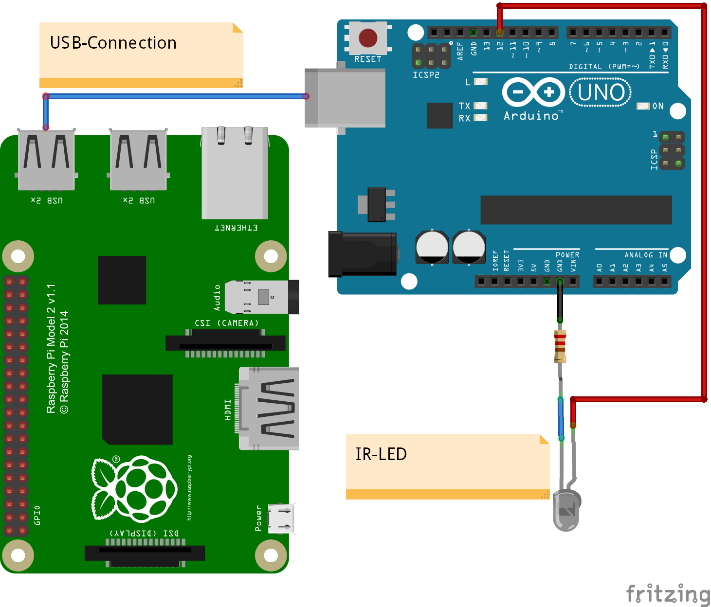
Arduino UNO has an USB connection, which supports serial connection to a host computer. The arduino can be used as a IO expander, connecting digital io lines, pwm, servo or adc-inputs directly to scratchClient and to scratch.
On digital inputs D2-D12, the firmware supports counters. The inputs are debounced and frequencies are possible till prox 50Hz.
This setup with scratchClient can be run on Raspberry or on windows, unless scratch 1.4 is used.
Powered by the USB-connection, the UNO provides 5V-compatible inputs/outputs. This is an advantage in some constellations. But do not connect these outputs directly back to the raspberry GPIO pins. And be careful on power consumption. Small servo can be operated, but larger current devices need external 5V supply.
The solution is also applicable to arduino NANO. This small board offers a breadboard friendly layout.
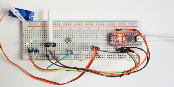
Sample setup with a NANO, 3 LED, Poti, Button, Servo and NANO on breadboard. Host computer (Raspberry Pi or Windows) not shown.
The functionality presented here is not a bridge to mesh network, propagating events and sensor updates into the arduino. There is a custom arduino sketch needed which only exposes the IO resources, but does not allow for additional logic in arduino (yet).
Configuration of the io-pins (direction, pullup, pwm, servo) and adc-pins (whether used or void) is controlled by scratchClient through configuration.
The scratch names used are configurable in configuration too. This is common functionality of the framework.
Communication between host computer and arduino is by a serial line USB connection. Speed is 115200 bd, set line end to LF . The arduino protocol uses as short as possible command sequences.
Example:
pwm:4,90\n sets PWM channel 4 to 90.
p:4,90\n is the same command, abbreviated.
With
help\n
a summary of command features can be printed.
The protocol is build on readable ascii sequences, which makes debugging with arduino serial monitor easy (set line end feature to ‘newline’). This also allows to fully drive the protocol from the serial console.
The command parser uses a state based approach for speed purpose. Each received char needs to be processed as quick as possible, which is only possible with a state machine.
First implementation was collecting chars in buffers and on a LF-char the data have been compared to the different commands. This needed many expensive strcmp-operations, decoding the parameters was done by sscanf. This approach limited throughput.
The parser code is generated by a python program and the resulting code is then inserted into the arduino C-program.
The code for arduino, sample configuration for scratchClient and sample scratch program is in the scratchClient distribution.
For setup, follow the steps described below.
Step 1, program the firmware to arduino
Start arduino IDE software, load arduino/arduinoUno/arduinoUno.ino from the scratchClient distribution and program it into the UNO or NANO. This needs to be done only once. I run this from a windows machine, but arduino IDE should also be supported on Raspberry Pi.
The LED13 on the arduino should blink at 5Hz, quite fast. This indicates that the firmware is running, but did not yet receive configuration.
On a serial monitor, you should see:
arduino sending@115200 Bd
arduinoUno, version 2016-02-21
config?
config?
config?
The config?-request is printed each second until the host provides configuration commands. Close serial monitor in order to allow scratchClient to have access to the serial line.
With ‘help’ from the serial monitor (use newline for line end separator), the arduino provides the list of supported commands.
Step 2, sample Hardware setup
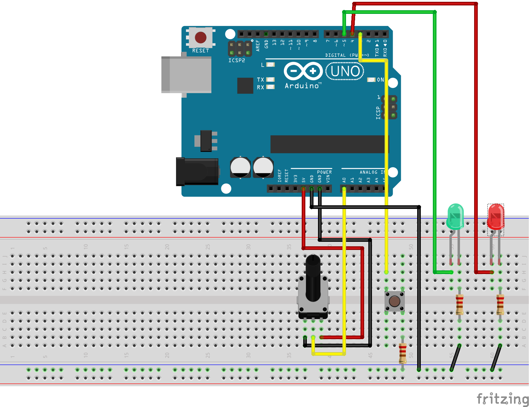
The hardware uses a potentiometer (2k to 10k are ok) on AD0. On D3, there is a button connected. The other side is having a 1k-resistor to GND (just in case the output is configured as an output, this prevents damage to the IO).
Two LED are for output. The green LED is on a PWM-output D5, so it can be dimmed.
This setup is a sample. The functionality of all the inputs and outputs are defined by configuration in scratchClient. See config/config_arduino_uno.xml for a sample.
Step 3, connect arduino with USB-Line to RaspberryPi or windows computer.
On raspberry, lookup /dev /tty* connections and configure the UNO serial device in config/config_arduino_uno.xml-File.
For windows, you see the COMn-Device used in deviceManager. Configure this name in config file.
An arduino UNO or NANO needs a few 20mA when running, LEDs add prox 10mA each. This current is provided by USB port of host computer. If more power is needed, then an external power supply is needed.
Step 4, start scratchClient with configuration
cd ~/scratchClient
python src/scratchClient -c config/config_arduino_uno.xml
After a short while, the LED13 should start blinking at 0.5Hz, quite slow. This indicates that configuration was downloaded and system ready to be used. The Tx, Rx-LED on arduino should flash now and then. Quite often when you turn the potentiometer, or when you press the button.
Step 5, start scratch with sample program
There is a sample program in scratch/arduinoUno/arduino.sb
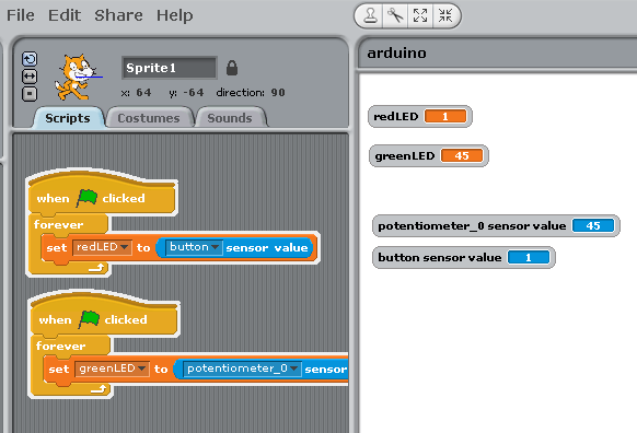
The program takes the button input and controls the red LED with it.
The value from the potentiometer is used to set the pwm-rate and dims the green LED. The mapping of the variable names or sensor names to IO-points is done in config file.
ID-Code
The arduino can have an ID-code in eeprom, which can be set by serial line console and read out from remote. This ID allows the host raspberry to recognize the arduino and provide configuration for this special device. This is a very nice feature for school setups where some experiments are hard wired and need fixed configuration. There is a starter code available which checks the connected arduino, and presents the related config files for scratchClient to start. I am working on an extension to start scratch with a basic program too. Avoids a lot of handling errors in school, especially where the focus is on driving an experiment and coding is not so important.
The serial protocol allows to read and set the ident code.
cident?\n request idcode
cident:<char16>\n write idcode
Configuration Tool
The setup of the xml config file is not very intuitive. There is a config gui available to edit the file. The tool is started with
cd ~/scratchClient/tools
java -jar scratchClientConfig.jar
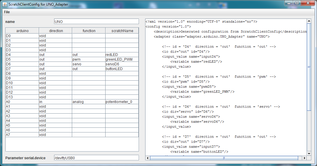
The left side of the frame is the editor pane which allows to select the various functions for the arduino. The right panel is a view-only display of resulting xml data.
Existing files can be loaded, but current version (2017-02-10) only allows to handle one adapter of type ‘UNO_Adapter’.
Constraints
The adc-channel is limited to 10Hz update rate. There is averaging for three samples per measurement value transmitted.
The digital inputs are limited to 20Hz update rate.
The adc-channel of atmel328 allow for analog inputs or GPIO usage.
PWM pulses are created with arduino native analog_write on the digital pins. Value range for pwm are 0..255.
Servo pulses are created with Servo-library. See limitations of this library in Arduino Servo [https://www.arduino.cc/en/reference/servo]. Input values for servo are 0..180.
Configuration is not persisted in the arduino (but downloaded from the the scratchClient adapter); there is no interface for custom logic (for fast sensors).
Configuration is requested to be sent from PI or windows to arduino on reset of arduino. If scratchClient configuration is changing, then a reset of arduino is needed to make this active. As in most cases a hardware change is made with arduino disconnected from power (either USB cable or power plug), this is only a small limitation.
This scratchClient adapter runs also on windows platform. This allows setups where a windows computer, scratch 1.4 for windows are using IO connections.
Other libraries
Recently I discovered ‘nanpy’, a python library to control an arduino by python programs.
Updates
Updated 2017-03-15, Counter for digital inputs added.
Updated 2017-02-10, Config tool for xml config file included.
Updated 2016-02-21, Some remarks on state based parser, command sets.
Updated 2016-02-15, added servo capability.
