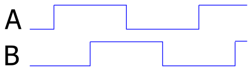
Rotary encoders produce two waveforms, shifted by 90 degrees, which allow to decode position and direction of movements.
The two waveforms look as given in the chart. Only one direction is shown.
In raspberry pi forum, someone asked for the performance of a python program to decode these signals.
The code used to validate python program is
import RPi.GPIO as GPIO
import time

GPIO.setmode (GPIO.BCM)
GPIO.setwarnings(False)
pin_A = 22
pin_B = 27

Encoder_Count = 0      # Encoder Count variable

def do_Encoder(channel):
    global Encoder_Count
    if GPIO.input(pin_B) == 1:
        Encoder_Count += 1
    else:
        Encoder_Count -= 1

GPIO.setup (pin_A, GPIO.IN, pull_up_down=GPIO.PUD_UP)         # pin input pullup
GPIO.setup (pin_B, GPIO.IN, pull_up_down=GPIO.PUD_UP)         # pin input pullup

GPIO.add_event_detect (pin_A, GPIO.FALLING, callback=do_Encoder)   # Enable interrupt

lastCount = 0
t0 = time.time()
while(1):
    t0 += 20
    time.sleep(t0 - time.time())
    print ("{e:d} diff={d:d}".format(e=Encoder_Count, d = Encoder_Count-lastCount))
    lastCount = Encoder_Count
As a driver for these signals I use an arduino DUE.
The results for the python code on a Raspberry Pi 3 are
freq       exp     measure
   10Hz    200         200
  100Hz   2000        2000
  500Hz  10000       10000  +-2
 1000Hz  20000       20000 +-25
 2000Hz  40000       40000 -40
 3000Hz  60000       60000 -660
 5000Hz 100000     -100000 +-20, but received negative values, so python too slow to get matching level
Up to 3.000 pulses, the results are quite reliable. For a 1.000RPR encoder, these are 3 rotations per second.
Usually I recommend to use an atmel328-processor as a slave processor to handle time sensitive operations. With an arduino UNO, 16MHz, the results are precise up to 15.000Hz.
There is no complete arduino needed. A bare atmel328, clocked from GPIO4, using level shifters for clock and serial line, would be a cost effective solution.
The sketch uses interrupts for the event inputs:
const byte ip2 = 2;
const byte ip3 = 3;
volatile long counter = 0;

void ip2Int() {
  byte iip2 = digitalRead(ip2);
  byte iip3 = digitalRead(ip3);
  if ( iip2 == 1 ) {
    if ( iip3 == 1 ) {
      counter --;
    }
    else
    {
      counter ++;
    }
  }
  else // ip2 == 0
  {
    if ( iip3 == 1 ) {
      counter ++;
    }
    else
    {
      counter --;
    }
  }
}

void ip3Int() {
  byte iip2 = digitalRead(ip2);
  byte iip3 = digitalRead(ip3);
  if ( iip2 == 1 ) {
    if ( iip3 == 1 ) {
      counter ++;
    }
    else
    {
      counter --;
    }
  }
  else // ip2 == 0
  {
    if ( iip3 == 1 ) {
      counter --;
    }
    else
    {
      counter ++;
    }
  }
}

void setup() {
  Serial.begin(115200);
  Serial.println("encoder");

  pinMode(ip2, INPUT);
  pinMode(ip3, INPUT);

  pinMode( 13, OUTPUT);
  pinMode(pin_sync, INPUT );

  attachInterrupt(digitalPinToInterrupt(ip2), ip2Int, CHANGE);
  attachInterrupt(digitalPinToInterrupt(ip3), ip3Int, CHANGE);
}

void loop() {
  long c0 = 0;
  noInterrupts();
  c0 = counter;
  interrupts();

  Serial.println(c0);
  delay(10000);
}
This code runs up to 15.000Hz, at 20.000 Hz it fails.
An obvious optimization is to change the interrupt routine and avoid the digitalRead-function for the atmel328-processor.
void ip2Int() {
  uint8_t pd = 0b00001100 & PORTD;  // pins 2,3 are PD2, PD3
  if ( pd == 0b00001000 || pd == 0b00000100 ) {
    counter ++;
  }
  else {
    counter --;
  }
}

void ip3Int() {
  uint8_t pd = 0b00001100 & PORTD;
  if ( pd == 0b00001100 || pd == 0b00000000 ) {
    counter --;
  }
  else {
    counter ++;
  }
}
This code is much faster and update rates till 50.000Hz work perfect.
With handcrafted assembler code for the interrupt-routine I would expect to extend performance even more.
Last option investigated was an arduino feather M0 board running at 48MHz.
This produces good results up to 30.000Hz, at 40.000Hz there are failures. With the results from optimized atmel328-code, there is quite a lot of optimization expected.
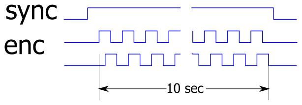
For the fast running signals, timing accuracy is crucial. To work around this problem, a sync pattern was used: an additional sync signal indicated start and end of measurement from generator to measurement device. Pulse sequence was 10 sec in each case.
For faster signals, either optimized assembler code needs to be used, or a hardware solution with a FPGA.
Updated 2017-02-19: optimized atmel code.