Annual school preparation needs to prepare some SD card with most current software, the current tutorials and some specific setup for scratchClient software.
There is standard answer you get when asking for the best procedure doing this: clone images using linux ‘dd’ tool.
Unfortunately this does not work when there are a SD cards which differ in size. And nevertheless it is needed to have a reference setup somewhere on a (laptop)-computer which allows to copy the data at least to one of the cards. So I decided to set up the SD card images using a headless PI and no manual operations on the target device.
This article shows some details about the scripting used.
Basic Procedure
The basic procedure is
- prepare the data (tutorials, custom config, software) in a file system on a remote computer.
- have sd cards with off-the-shelf raspbian prepared. WinDiskImager is used to prepare these. Which is a quick procedure, as these images are typically around 3GB in size.
- Insert sd car into pi, power and start script.
- Write some blog about scripting SD card setup.
Tooling
The automation of these tasks is performed in ‘ant’. SSH access and SCP are essential for controlling the remote raspberry.
Ant is available standalone. As I use ‘eclipse’ on a laptop for most of my programming tasks, ant is easily available.
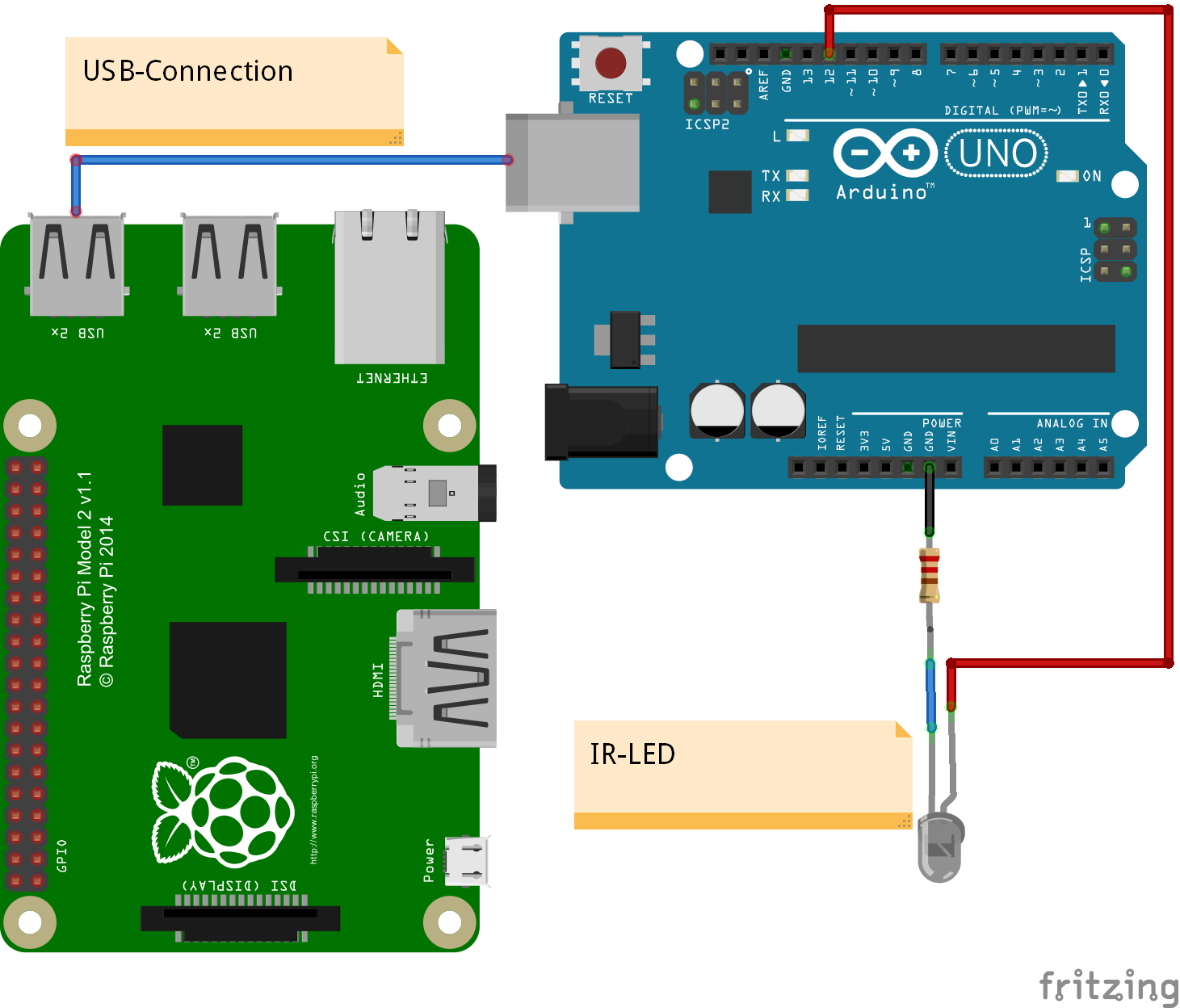
The host computer controls a PI by ssh commands. This Pi is connected by network. The local DHCP-Server assigns fixed IP address to this Pi. One card after the other is inserted into the SD slot, Pi gets power and the script is started on laptop.
Script desription
In the script, first step is to get root access from remote. In earlier releases of raspbian < mai 2016, it was possible to create root user and have root access through ssh. In current releases, the /etc/ssh/sshd_config does not allow root user access by password. The setting ‘PermitRootLogin’ does not allow this. The workaround is to use key based authentication. The keys need to be copied to the target system first.
<antcall target='passwd.root' />
 <antcall target='key.deploy.pi' />
 <antcall target='key.deploy.root' />
Creating the root user can be performed by standard pi user. A shell file is created locally, transferred to target and executed there.
    <target name="passwd.root">
        <echo file="passwd.sh">
            <![CDATA[passwd root <<EOF
${root.password}
${root.password}
EOF
]]>
        </echo>
        <scp_l2r_pi local="passwd.sh" remote="/home/pi/passwd.sh" />
        <delete file="passwd.root" />

        <ssh_exec_pwd_pi command="sudo sh passwd.sh" />
        <ssh_exec_pwd_pi command="rm passwd.sh" />
    </target>
The commands scp_l2r_pi (scp local 2 remote, user pi) and ssh_exec_pwd_pi (ssh exec, passwort authentication, user pi) are macro definitions which hide all the details .
    <macrodef name="scp_l2r_pi">
        <attribute name="local" default="NOT SET" />
        <attribute name="remote" default="NOT SET" />
        <sequential>
            <scp remoteTofile="${pi.user}:${pi.password}@${pi.host}:@{remote}" file="@{local}" failonerror="true" verbose="${verbose}" trust="yes" />
        </sequential>
    </macrodef>
    <macrodef name="ssh_exec_pwd_pi">
        <attribute name="command" default="NOT SET" />
        <attribute name="failonerror" default="true" />

        <sequential>
            <sshexec command="@{command}" failonerror="@{failonerror}" host="${pi.host}" username="${pi.user}" password="${pi.password}" trust="yes" />
        </sequential>
    </macrodef>
Similiar macros exist for key authentication, which is possible for root when ssh keys are available and root user is created.
The key distribution is done with password authentication and pi-user access only.
    <target name="key.deploy.pi">
        <ssh_exec_pwd_pi command="[ -d /home/pi/.ssh ] || mkdir /home/pi/.ssh" />
        <scp_l2r_pi remote="/home/pi/.ssh/authorized_keys" local="key/id_rsa.pi.pub" />
    </target>

    <target name="key.deploy.root">
        <scp_l2r_pi remote="/home/pi/authorized_keys" local="key/id_rsa.root.pub"  />
        <ssh_exec_pwd_pi command="echo '${root.password}' | sudo -S mkdir /root/.ssh" failonerror="false" />
        <ssh_exec_pwd_pi command="echo '${root.password}' | sudo -S cp /home/pi/authorized_keys /root/.ssh/authorized_keys" />
    </target>
The root file deployment is done into a pi-user file first. Then with copy commands, the transfer into the target dir is performed. Here ‘sudo’ is needed.
raspi-config non interactive
The tool ‘raspi-config’ assembles all the knowledge about the config files and settings needed to tweak the system. Since some time > mai 2016, there is a command line switch allowing to use the tool from command line. There is no documentation, but the programming is straightforward. Here the code to set serial (off) and to spi (on).
    <target name='set_serial' description="disable serial">
        <echo>set Serial off</echo>
        <ssh_exec_key_root command="raspi-config nonint do_serial 1" />
    </target>

    <target name='set_spi'>
        <echo>set SPI on</echo>
        <ssh_exec_key_root command="raspi-config nonint do_spi 0" />
    </target>
The parameters ‘0’ and ‘1’ are opposite to their human meaning, but these values are found inside the script. So ‘do_serial 1’ switches serial line off.
    <target name='set_overclock_high'>
        <!-- High is both available on pi 2 and pi 3 -->
        <ssh_exec_key_root command="raspi-config nonint do_overclock High" />
    </target>
For completeness also the scripting for the overclock setting.
Update system software
One of the basic steps is the update of the system.
        <sequential>
            <echo>Packages aktualisieren</echo>
            <ssh_exec_key_root command="apt-get update" />
            <ssh_exec_key_root command="apt-get upgrade -y" />
        </sequential>
Transfer of data, code, config
Finally, the transfer of the tutorials, software and all the other things is done. Compared to the overhead needed a quite short task.
            <sequential>
                <echo>copy tutorials and other</echo>

                <scp failonerror="true" verbose="${verbose}" todir="${root.user}@${pi.host}:/home/pi" keyfile="${basedir}/key/id_rsa.root" trust="yes">
                    <fileset dir='data'>
                        <include name='**/*' />
                    </fileset>
                </scp>
                <ssh_exec_key_root command="chgrp -R pi /home/pi/" />
                <ssh_exec_key_root command="chown -R pi /home/pi/" />
            </sequential>
Time measurements
The execution time of the script is dependent on the amount of packages downloaded from the web into the computer. For this setup, the raspbian distribution is from mai 2016 and the setup time was sept 2016, so quite a lot of packages needs to be updated.
| target system |
overclock |
SD card |
time |
| PI 2 |
no |
6MB/s |
41 min |
| PI 2 |
fast |
6MB/s |
38 min |
| PI 3 |
fast |
6MB/s |
24 min |
| PI 3 |
fast |
16MB/s |
15 min |
tldr
With automation by ‘ant’, SD cards are set up using a headless pi installation and no manual interaction.

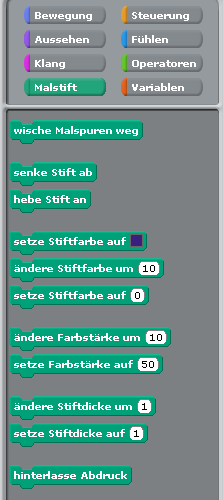 Wenn man Figuren bewegt, dann können diese bei der Bewegung Linien auf die Bühne malen. Dazu sind die ‚Malstift‘-Blöcke vorhanden.
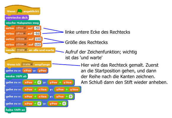

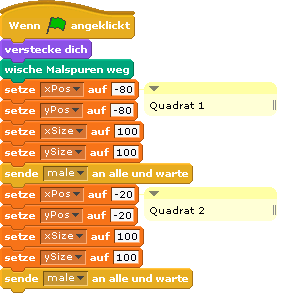
 Bisher waren nur sehr wenige Quadrate auf der Bühne. Wenn man sehr viele Quadrate haben möchte, dann wird das ‚Untereinanderschreiben‘ von Zeichenbefehlen sehr mühsam. Dafür sollten Programmschleifen verwendet werden.
 Es ist klar, dass man „wiederhole“-Schleifen braucht.
 Dieses Beispiel kann aus den ineinander geschachtelten Rechtecken abgeleitet werden.