Category Archives: scratch

Zusatzaufgabe scratch, Malprogramm

Schreibt ein einfaches Malprogramm. Mit den Pfeiltasten soll ein kleiner Punkt bewegt werden können. Mit der Leertaste soll ein Stempelabdruck erzeugt werden können.

Also Schritt 1: Bewegen mit den Cursortasten, Stempeln mit der Leertaste. Erst wenn das funktioniert, dann erst den zweiten Schritt beginnen.

Der zweite Teil der Aufgabe ist schwieriger: fügt eine Abspielfunktion hinzu, welche die Punkte nocheinmal wiedergibt wie im Video.

Schritt 2: Aufzeihnen und Abspielen zufügen.

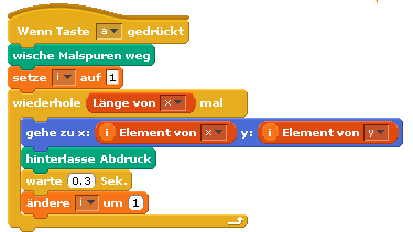
Dazu zwei Listen anlegen (x und y) und die Positionen  des Punktes hinzufügen beim Stempeln.
x_array

Für das Abspielen dann den ersten, zweiten, dritten Eintrag abholen und den Punkt neu positionieren und stempeln.

x_replay

Klar ? Ausprobieren !

Zusatzaufgabe scratch, Grundrechnen

Grundrechenarten üben, erst mal einfach, dann kompliziert.

Einfach:

Schreibt eine Anwendung, mit der jüngere Schüler die Grundrechenarten üben können.

(1) das Programm soll Aufgaben anzeigen, z.B. 3+4. Der Schüler gibt dann die Antwort ein. Wenn richtig, dann Punkte hochzählen und ein Lob ausgeben !

Benutzt Zufallszahlen für die beiden Zahlenwerte. Und Zufallszahlen für den Operator +, -, *, /. (Das ist eine kleine Denksportaufgabe, wie man mit Zufallszahlen den Operator auswählt.)

Und jetzt wird es komplizierter:

(2) Der Bereich der Eingabezahlen soll zwischen 1 und 10, 0 und 50, -10 und 100 sein. Das soll auf der Bühne umschaltbar sein.
(3) Da das Programm für jüngere Schüler ist, sollen die Ergebnisse der Subtraktionen immer grösser oder gleich 0 sein. Die Divisionen sollen immer ganzzahlige Ergebnisse ergeben.
(4) Wenn es Fehler gibt, dann soll genau diese falsch eingegebene Aufgabe später nochmals ausgegeben werden.

Mit der Anforderung (1) anfangen, dann (2). Die Anforderung (3) ist schon schwieriger und die (4) ist schon recht kompliziert.

Zusatzaufgabe scratch, Geometrie

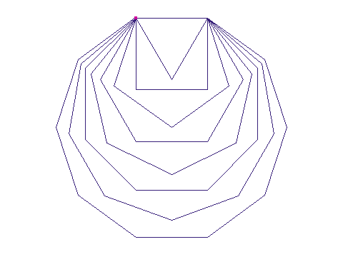
Geometrie mal praktisch: zeichne ein Dreieck, Viereck, Fünfeck, Sechseck, Siebeneck, Achteck, Neuneck und Zehneck. So wie hier dargestellt:

stage_N

Darf auch gerne etwas bunter sein !

Hier kommt das Linienzeichnen zur Anwendung.

Diese Aufgabe ist aus http://www.scratch.ie/sites/all/themes/scratch_theme/resources/newworkbook/Module5.pdf entnommen.


Zusatzaufgabe scratch, Flächen

Flächenermittlung einer unregelmässigen Figur.

Flächen von Figuren kann man berechnen, wenn es Rechtecke, Quadrate, Kreise oder ähnlich sind, Bei unregelmässigen Figuren ist das Ausrechnen meist nicht möglich. Man kann dann z.B. ein Millimeterpapier drüberlegen und die Kästchen abzählen.

Mit dem Computer kann man die Pixel abzählen, und hier ist die Aufgabe dazu.

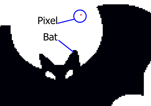
Wie macht man das: Die Pixel-Fläche eines Sprite soll abgezählt werden. Ein zweites Sprite wird zum Abmessen verwendet. Das zweite Sprite ist möglichst klein, also nur ein Pixel gross.

Alle Gruppen verwenden die Fledermaus, deren Pixel-Fläche bestimmt werden soll.

bat_stage_explained

Man bewegt das Pixel-Sprite zeilenweise über die Bühne und wenn das Pixel die Fledermaus berührt, dann erhöht man einen Zähler. Wenn dann das ganze Bild abgetastet ist hat man die Fläche in Pixeln ermittelt.

Damit das nicht allzu lange dauert sollte man nur die Koordinaten (-100, -100) bis (100, 100) abtasten.

Also

– Fledermaus, Bat importieren.
– neues Sprite (nur ein Pixel!), rot ist ganz gut, damit man das kleine Pixel überhaupt sieht.
– Sprite in Zeilen bewegen, im mittleren Bereich des Bildschirmen (-100,-100) bis (100,100). Die Bat muss in diesem Bereich positioniert werden.
– Nach jeder Bewegung des Pixels einen Stempelabdruck erzeugen. Damit man sieht, wie das Programm funktioniert.
– Das Programm läuft relativ lange. Das braucht etwas Geduld. Im Präsentationsmodus läuft das Programm schneller und noch schneller, wenn die Variablen nicht eingeblendet werden.

Das Programm muss überprüft werden. Dazu legt man in der Bat-Sprite ein zweites Köstüm mit einem Rechteck an und berechnet dessen Fläche. Dann lässt man das Programm laufen und das Ergebnis sollte dasselbe sein wie die Rechnung.

Wieviele Pixel ist die Fledermaus gross ?

Wieviele Bewegungen muss das kleine Pixel machen ?

Wie lange dauert das Scannen ? (Benutze die Stoppuhr um das zu ermitteln).

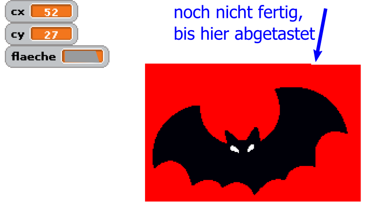
bat_scan_progress

Bühne während des Abtastens. Spooky !

Flächenermittlung MonteCarlo-Methode

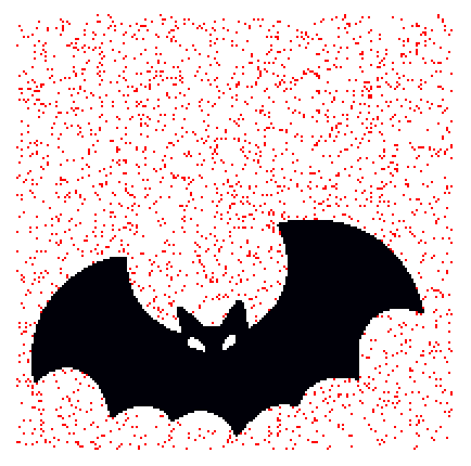
Das Abscannen dauert sehr lange, ist aber genau. Es gibt schnellere Verfahren, die dafür ungenauer sind. Dabei wird nicht mehr zeilenweise abgetastet, sondern das Pixel wird mit Zufallszahlen im Bereich (-100, -100) und (100,100)  positioniert. Dann werden nur wenige Pixel gemessen, hier z.B. nur 3000 Pixel.

Wegen der verwendeten Zufallszahlen werden solche Verfahren nach einer Stadt benannt, in der es ein Spielkasino gibt.

Das Ergebnis ist nicht ganz genau, aber deutlich schneller als das Abtastverfahren. Aber es benötigt im Vergleich zum Scannen weniger als in Zehntel der Zeit.

bat_mc_3000

Monte Carlo-Verfahren, 3000 Punkte

Das Ergebnis ist nur um ein Prozent ungenau. Dafür, dass die Rechenzeit sehr viel kürzer ist ist das sehr gut.

Aufgabe: Ermittle die Fläche mit dem Zufallsalgorithmus.
– positioniere das Pixel 3000 mal zufällig in der x-Achse und y-Achse in (-100, -100) bis (100,100).
mc_position
– Zähle, wie oft das Pixel die Fledermaus berührt in einer Variable ‘ci’.
– Die Fläche ist dann ca (201*201) * ci / 3000. Warum 201 ?

Sense Hat, Astro Pi connected to scratch

Sense Hat (announcement by raspbery pi foundation) is an add on board for PI2, which supports environmental sensors for temperature, pressure and humidity. There is an IMU-sensor included. And a fancy 8×8 RGB-LED matrix. And a small joystick which provides cursor keys and the enter key for the center button.

The software to drive this board is wrapped in a python API. This APi is handy to be used for scratchClient and connect it to scratch.

The adapter is adapter.senseHat_adapter.SenseHat_Adapter.

LED Matrix

Events are ‘clear’, setPixel_xy’ and ‘clearPixel_xy’.

‘clear’ is pretty straightforward and clears the matrix to blank.

The pixel operations need variables to be set before the setPixel can be performed.

procedureCall
x and y position needs to be set and the color needed. The event sense_led_xy_on is mapped to setPixel_xy by scratchClient. This mapping is done in the configuration for this adapter (scratchClient/scratch/senseHat/config_senseHat.xml).

        <input name= 'clear'>
            <broadcast name='sense_led_clear'/>
        </input>
        
        <input name= 'setPixel_xy'>
            <broadcast name='sense_led_xy_on'/>
        </input>
        
        <input name= 'clearPixel_xy'>
            <broadcast name='sense_led_xy_off'/>
        </input>

The commands available in scratch are the <broadcast/> elements. These all have the prefix ‘sense_’.

Color supports basic colors in plain english (red, green, white, blue, and some more) and ‘#aabbcc’ which is hex notation in red, green blue. In the  scratchClient documentation are the details, look for the ‘colorType’-definition in chapter ‘Adapter Data Types’ .

In my experiments, I found that small rgb-values for the LED, e.g. #030303, which is red=3, green=3, blue=3 are not displayed, but leave the LED dark. Obviously the API is doing some gamma correction and discards small values. Try higher values if you run into this problem. #303030 seem to be smallest values available.

For the clearPixel call, no color needs to be set.

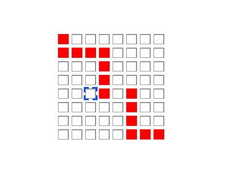
There is a scratch sample application scratchClient/scratch/senseHat/sense_hat_led.sb which allows to set/clear pixel in a (hopefully) intuitive way. Move the blue cursor mark with cursor keys and toggle the LED by blank key.

led_control

Stage printout

The joystick on senseHat can be used to move the cursor around. Unfortunately the center button sends ‘enter’, which is the ‘green flag event’ in scratch and restarts the code. Thus the toggle LED is mapped to the blank bar on keyboard for this sample.

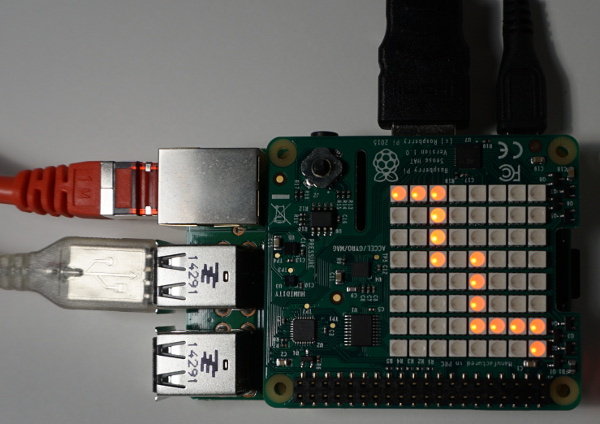
led-matrix

A LED pattern, camera shutter time 1/60 sec

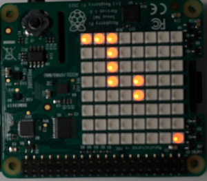
led-matrix-2

Same LED pattern, camera shutter time 1/100 sec displaying only part of the LED

Took me  a while to identify the problem in the second photo: the exposure time was 1/100 sec, so the refresh rate of 80Hz for the LED produces fake ‘missing LED’ on the sense hat.

Environmental Sensors

The humidity, pressure and temperature values are sent at a limited frequency to scratch. And only when values change. For this adapter, the precision of values sent is limited to one decimal digit. This reduces communication effort and system load by 10 percent.

The temperature value and dependent from this the humidity sensor suffers from heating of the hat board by the primary processor. On my desktop, the temperatures reported have been prox 10 degree too high. There are reports of people who separated the Pi and hat by a ribbon cable and got better results.

IMU Sensor

The gyro, accel and compass sensor contribute to the orientation signals, which are sent as orientation_yaw, orientation_roll and orientation_pitch to scratch. These values are quite stable. These values also are sent only at a limited frequency and reduced precision to one digit number. But 1/10 degree is good for most purposes.

Installation of prerequisite software

The board needs software to be installed. See the installation instructions on the API side

Start scratchClient

cd ~/scratchClient
sudo python src/scratchClient.py -c scratch/senseHat/config_senseHat.xml

Remote scratch connection, 2×3 multipanel setup

With scratchClient, it is possible to connect multiple scratch instances with events. ScratchClient can combine this feature with other adapters, as GPIO or alike.

To demonstrate a ‘chain reaction’ type application, I have connected six scratch screens in a 2*3-array to have a red dot traverse the screens.

As I do not own 6 hdmi-monitors for scratch, I have collected 6 vnc-sessions with 600*400-resolution on a desktop computer. The video is taken from this machine.

Each scratch instance sends a specific start broadcast to the next scratch instance to trigger the display-move-hide sequence there. So Instance 0 sends ‘start_1’, instance 1 sends ‘start_2’ and so on. Instance 5 sends ‘start_0’ and the sequence starts again.

The sample is in the scratchClient-distribution, scratch/chainReaction-folder. If you want to run this sample, you need six raspberry computers. Start scratch/chainReaction/reaction_0.sb on each of the raspberryPi. Change the value of ‘whoami’ to 0, 1, 2.. 5 and arrange the screens in

0, 1, 2
5, 4, 3

order.

On one of the computers, the scratchCommunicationServer needs to be started.

cd  ~/scratchClient
python src/scratchCommunicationServer.py

For each of the computers, there is a distinct computer-specific config script. Adjust the

 <parameter name="server" value="192.168.2.90" />

in the config-files to match the ip-address of the server computer.

For computer 0, use config_start_0.xml:

cd  ~/scratchClient
sudo python src/scratchClient.py -c scratch/chainReaction/config_start_0.xml

and start scratchClient on other computers with config_start_<N>.xml, N=1..5.

The remote connection adapter can be combined with other adapters like GPIO or whatever needed. This is the reason to start the python application with sudo.

The current configuration combines the remote communication adapter with a GPIO output on GPIO18. This is a feature unique to scratchClient.

RFID Tag Reader

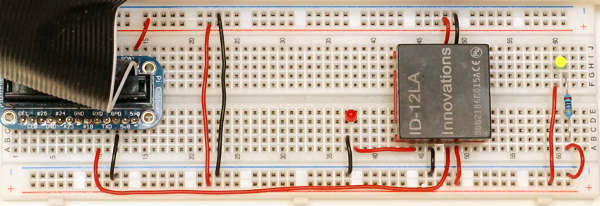
There are nice little tag reader devices available from ‘innovations’ as the ID-12LA. It works with the 125kHz cards or tags, does not need an external antenna and can work directly with Raspberry Pi. I recently got one on my desk and connected it to scratch.

For the setup, there is the possibility to connect it directly to Raspberry Pi serial port, or to buy an usb-adapter. I have choosen the simple way, but as the pin spacing is 2mm there is a breakout board needed to match a breadboard. I used some 2mm spaced sockets on the adapters and have the module pluggable.

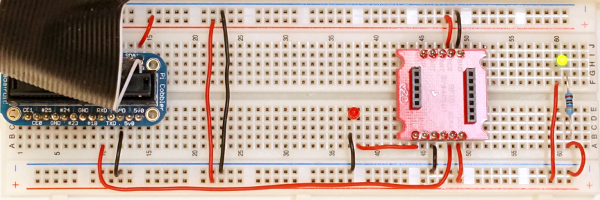
The two images show the breakout board without the modue and with the module. The yellow LED at the right is a ‘always on light’ used as a power indicator. Quite useful to see if a breadboard is connected.

rfid-setup_0

rfid-setup

For the connection to scratch a special adapter is needed for scratchClient. The adapter.serialAdapter.RFID_Reader_Adapter opens the serial port and extracts the Tag-Numbers from the byte stream. When data are available, these are sent to scratch. Then a broadcast event is published ‘rfid_available’. A sample config file is provided config/config_ID12LA.xml.

ScratchClient start is performed by

sudo python src/scratchClient.py -c config/config_ID12LA.xml

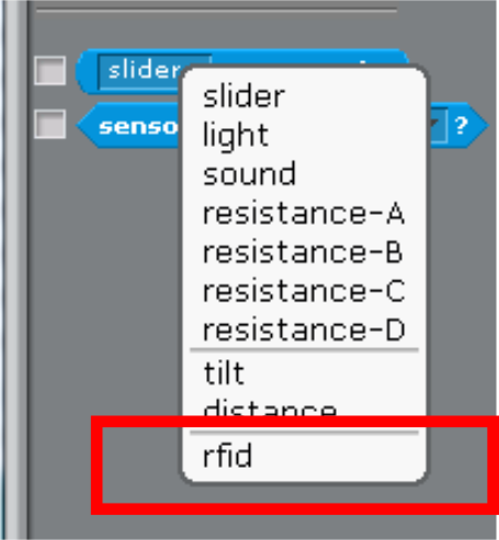
Start scratch 1.4, open ‘remote sensor connections’. When a tag or card is near the reader, then scratch should receive a variable ‘rfid’ containing a 10 bytes hex number.
sensor2

A sample program can record tags and associated names in an internal ‘database’, build from two lists. One list is for names, the other for rfid.

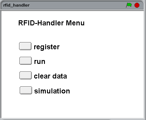
rfid_handler_menu

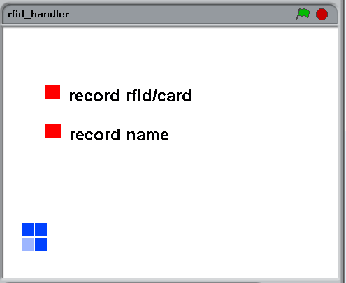
select ‘register’ to read in tags and names (from keyboard).

rfid_handler_record

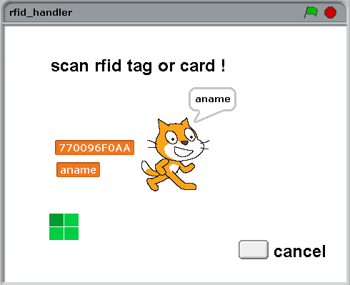
In ‘run’-screen, tags scanned are checked against the available rfid in rfids-list. When match exist, the cat tells the name found.

rfid_handler_run

The green/blue boxes are an indicator for read events. For each event, it should turn clockwise.

The ‘clear data’-Button clears internal data.

And for all the impatient people there is a simulation mode which populates the database with some dummy values. In run mode, the simulation displays a ‘random’-button which simulates input.

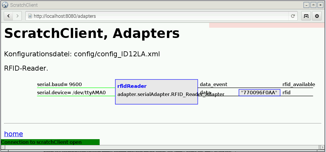
scratchClient can also be used to provide input to scratch. Open http://localhost:8080 and navigate to ‘adapters’.

scratchClient_adapters

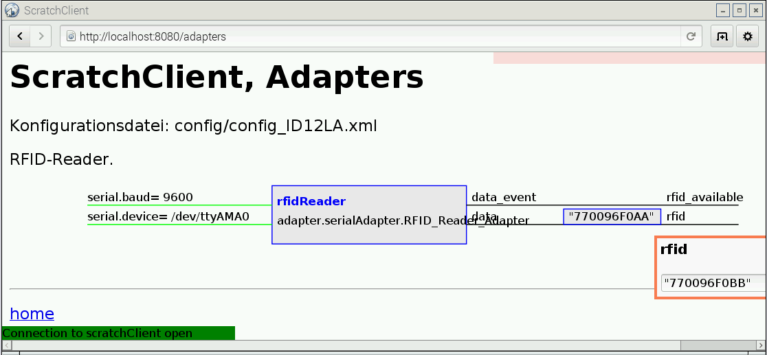
on the right hand side, there is lat value for rfid shown. The Quotes are mandatory here, as scratch needs to interpret values as strings. Click into the text field, you get an entry popup.

scratchClient_adapters_entry

Confirm the entry by ‘enter’. Then click on the rfid_available- string and a red blink rectangle confirms the event is sent to scratch.

The formatting of the class name in the adapter box is not perfect, will change this if there is some spare time.

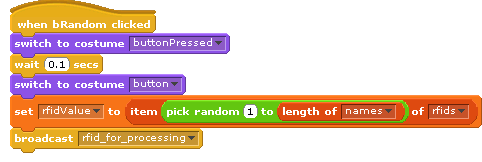
One feature in the scratch code is how the simulation data insertion is solved. It is not possible to overwrite sensor values. So when sensor values arrive, the data are copied to a global variable and a new broadcast is issued.

In the stage scripts, the input from the sensor is copied to a globale variable.

script

All code processing rfid data is based on ‘rfidValue’ and ‘rfid_for_processing’.

In the rButton-script, this global variable and event is produced.random

Downloads

scratchClient

scratch sample program

Arduino UNO, NANO connected to Scratch

Arduino UNO has an USB connection, which supports serial connection to a host computer. The arduino can be used as a IO expander, connecting digital io lines, pwm, servo or adc-inputs directly to scratchClient and to scratch.
On digital inputs D2-D12, the firmware supports counters. The inputs are debounced  and frequencies are possible till prox 50Hz.

This setup with scratchClient can be run on Raspberry or on windows, unless scratch 1.4 is used.

Powered by the USB-connection, the UNO provides 5V-compatible inputs/outputs. This is an advantage in some constellations. But do not connect these outputs directly back to the raspberry GPIO pins. And be careful on power consumption. Small servo can be operated, but larger current devices need external 5V supply.

The solution is also applicable to arduino NANO. This small board offers a breadboard friendly layout.
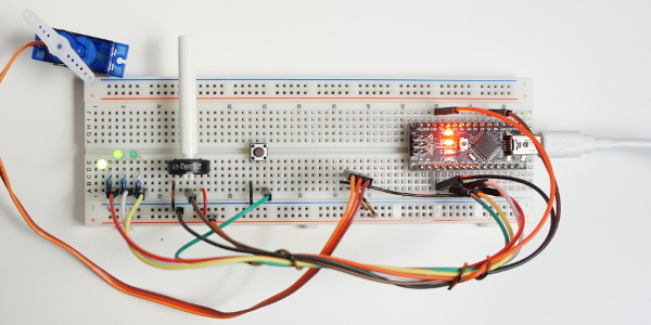
nano_breadboard

Sample setup with a NANO, 3 LED, Poti, Button, Servo and NANO on breadboard. Host computer (Raspberry Pi or Windows) not shown.

The functionality presented here is not a bridge to mesh network, propagating events and sensor updates into the arduino. There is a custom arduino sketch needed which only exposes the IO resources, but does not allow for additional logic in arduino (yet).

Configuration of the io-pins (direction, pullup, pwm, servo) and adc-pins (whether used or void) is controlled by scratchClient through configuration.
The scratch names used are configurable in configuration too. This is common functionality of the framework.

Communication between host computer and arduino is by a serial line USB connection.  Speed is 115200 bd, set line end to LF . The arduino protocol uses as short as possible command sequences.
Example:
pwm:4,90\n  sets PWM channel 4 to 90.
p:4,90\n is the same command, abbreviated.

With
help\n
a summary of command features can be printed.

The protocol is build on readable ascii sequences, which makes debugging with arduino serial monitor easy (set line end feature to ‘newline’). This also allows to fully drive the protocol from the serial console.

The command parser uses a state based approach for speed purpose. Each received char needs to be processed as quick as possible, which is only possible with a state machine.
First implementation was collecting chars in buffers and on a LF-char the data have been compared to the different commands. This needed many expensive strcmp-operations, decoding the parameters was done by sscanf. This approach limited throughput.

The parser code is generated by a python program and the resulting code is then inserted into the arduino C-program.

The code for arduino, sample configuration for scratchClient and sample scratch program is in the scratchClient distribution.

For setup, follow the steps described below.

Step 1, program the firmware to arduino

Start arduino IDE software, load arduino/arduinoUno/arduinoUno.ino from the scratchClient distribution and program it into the UNO or NANO. This needs to be done only once. I run this from a windows machine, but arduino IDE should also be supported on Raspberry Pi.

The LED13 on the arduino should blink at 5Hz, quite fast. This indicates that the firmware is running, but did not yet receive configuration.
On a serial monitor, you should see:

arduino sending@115200 Bd
arduinoUno, version 2016-02-21
config?
config?
config?

The config?-request is printed each second until the host provides configuration commands. Close serial monitor in order to allow scratchClient to have access to the serial line.

With ‘help’ from the serial monitor (use newline for line end separator), the arduino provides the list of supported commands.

Step 2, sample Hardware setup
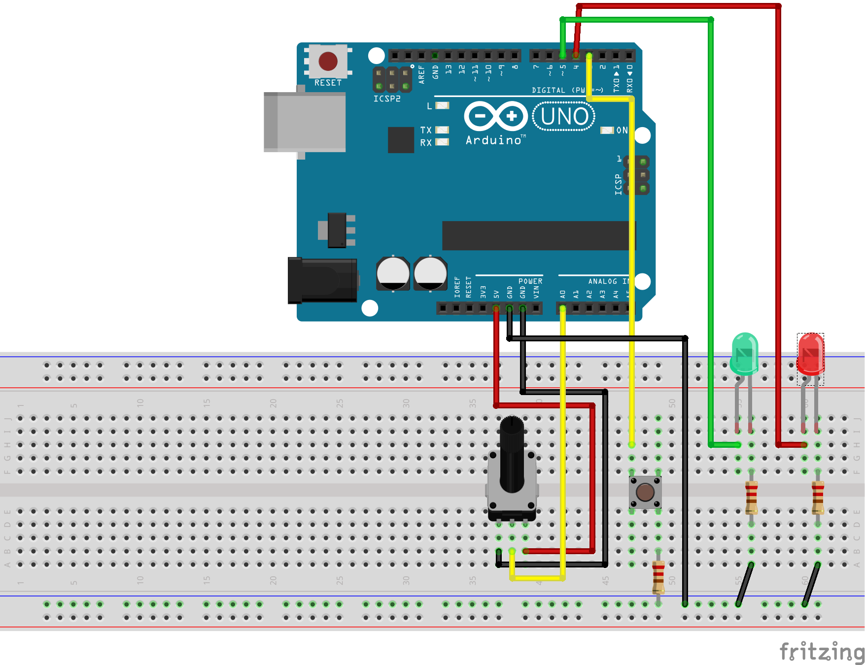
arduinoUno_Steckplatine

The hardware uses a potentiometer (2k to 10k are ok) on AD0. On D3, there is a button connected. The other side is having a 1k-resistor to GND (just in case the output is configured as an output, this prevents damage to the IO).
Two LED are for output. The green LED is on a PWM-output D5, so it can be dimmed.

This setup is a sample. The functionality of all the inputs and outputs are defined by configuration in scratchClient. See config/config_arduino_uno.xml for a sample.

Step 3, connect arduino with USB-Line to RaspberryPi or windows computer.

On raspberry, lookup /dev /tty* connections and configure the UNO serial device in config/config_arduino_uno.xml-File.

For windows, you see the COMn-Device used in deviceManager. Configure this name in config file.

An arduino UNO or NANO needs a few 20mA when running,  LEDs add prox 10mA each. This current is provided by USB port of host computer. If more power is needed, then an external power supply is needed.

Step 4, start scratchClient with configuration

cd ~/scratchClient
python src/scratchClient -c config/config_arduino_uno.xml

After a short while, the LED13 should start blinking at 0.5Hz, quite slow. This indicates that configuration was downloaded and system ready to be used. The Tx, Rx-LED on arduino should flash now and then. Quite often when you turn the potentiometer, or when you press the button.

Step 5, start scratch with sample program

There is a sample program in scratch/arduinoUno/arduino.sb
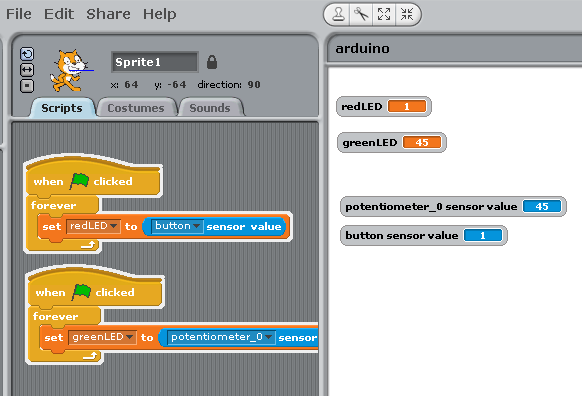
scratch

The program takes the button input and controls the red LED with it.
The value from the potentiometer is used to set the pwm-rate and dims the green LED. The mapping of the variable names or sensor names to IO-points is done in config file.

ID-Code

The arduino can have an ID-code in eeprom, which can be set by serial line console and read out from remote. This ID allows the host raspberry to recognize the arduino and provide configuration for this special device. This is a very nice feature for school setups where some experiments are hard wired and need fixed configuration. There is a starter code available which checks the connected arduino, and presents the related config files for scratchClient to start. I am working on an extension to start scratch with a basic program too. Avoids a lot of handling errors in school, especially where the focus is on driving an experiment and coding is not so important.

The serial protocol allows to read and set the ident code.

cident?\n     request idcode
cident:<char16>\n write idcode

Configuration Tool

The setup of the xml config file is not very intuitive. There is a config gui available to edit the file. The tool is started with

cd ~/scratchClient/tools
java -jar scratchClientConfig.jar
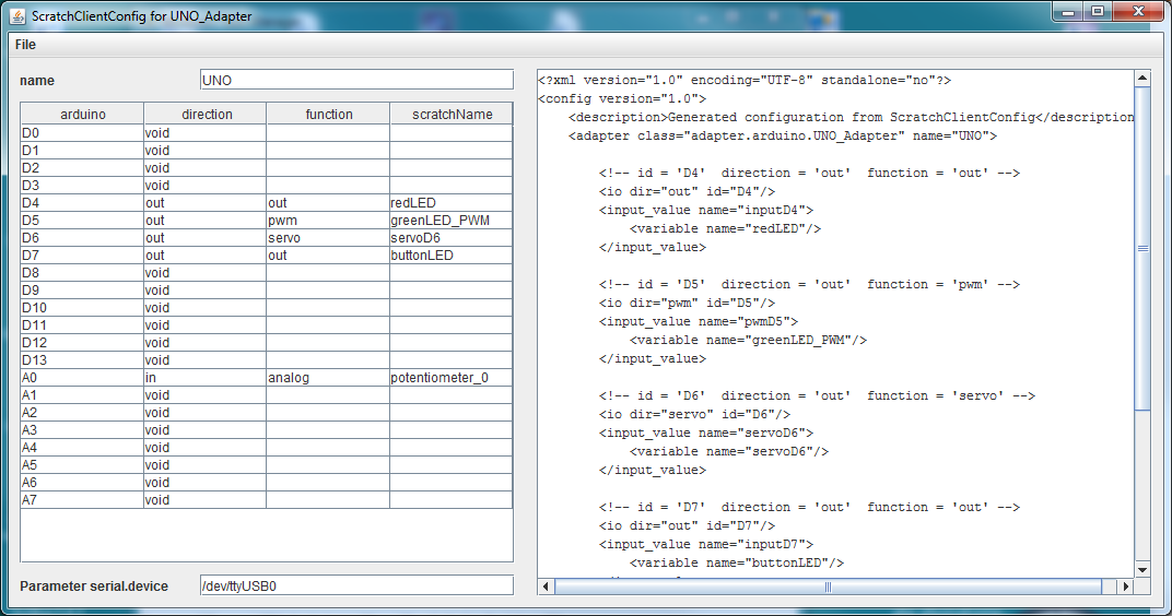
scratchclientconfig

The left side of the frame is the editor pane which allows to select the various functions for the arduino. The right panel is a view-only display of resulting xml data.

Existing files can be loaded, but current version (2017-02-10) only allows to handle one adapter of type ‘UNO_Adapter’.

Constraints

The adc-channel is limited to 10Hz update rate. There is averaging for three samples per measurement value transmitted.
The digital inputs are limited to 20Hz update rate.
The adc-channel of atmel328 allow for analog inputs or GPIO usage.
PWM pulses are created with arduino native analog_write on the digital pins. Value range for pwm are 0..255.
Servo pulses are created with Servo-library. See limitations of this library in Arduino Servo [https://www.arduino.cc/en/reference/servo]. Input values for servo are 0..180.
Configuration is not persisted in the arduino (but downloaded from the the scratchClient adapter); there is no interface for custom logic (for fast sensors).
Configuration is requested to be sent from PI or windows to arduino on reset of arduino. If scratchClient configuration is changing, then a reset of arduino is needed to make this active. As in most cases a hardware change is made with arduino disconnected from power (either USB cable or power plug), this is only a small limitation.

This scratchClient adapter runs also on windows platform. This allows setups where a windows computer, scratch 1.4 for windows are using IO connections.

Other libraries

Recently I discovered ‘nanpy’, a python library to control an arduino by python programs.

Updates

Updated 2017-03-15, Counter for digital inputs added.
Updated 2017-02-10, Config tool for xml config file included.
Updated 2016-02-21, Some remarks on state based parser, command sets.
Updated 2016-02-15, added servo capability.

aScratchPangoFont-Problem in ’14-Jan-15′ scratch

Remark: For raspbian ‘jessie’ and scratch “Scratch 1.4 (linux) of 2015-09-15”, this problem is solved.

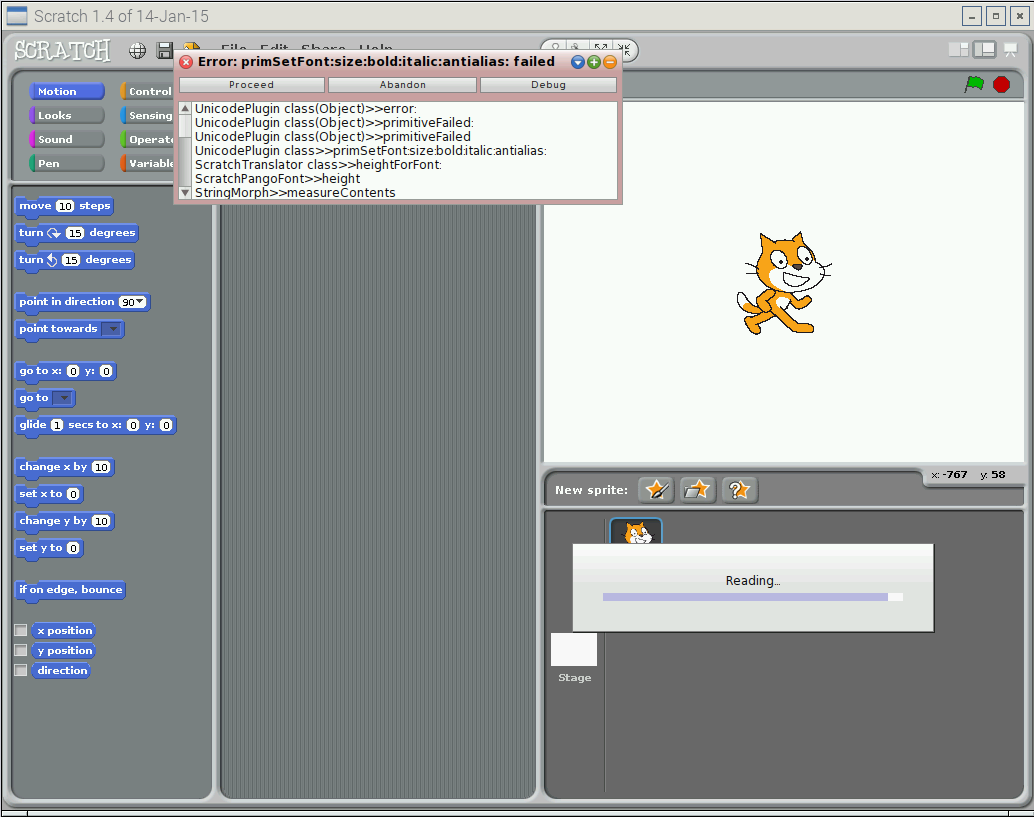
In scratch “Scratch 1.4 of 14-Jan-15”, as provided in raspbian for Raspberry Pi, there is a serious bug which prevents projects from loading. This affects scratch projects which are stored/reloaded multiple times, and only scratch projects which use texts in new created sprite costumes. The error popup is “primSetFont:size:bold:italic:antialias: failed”

error

Problem description

When loading a project, occasionally the following problem occurs

pango_001

The error message is “primSetFont”.

Reproduce the problem

In a new project, create a new sprite with the edit-button. Add a text to this sprite. Close the editor and save the project –> “x00”. Close scratch.

Start scratch, open project “x00”.
Open the costume with the font,, click to the ‘T’ext button. There is “a ScratchPan…” displayed. Close editor with ‘cancel’. Save project as “x01”. Close scratch.

Start scratch, open project “x01”, save as “x02”. Close scratch.
Repeat this till you reach “x05”. When loading “x05”, you should get this problem.

Technical Details

When looking to the project.sb-file of an affected project, there is a sequence shown where the original ‘DejaVu’-Font is wrapped into a ‘s ScratchPangoFont’ multiple times.
This wrapping seems to occur each time on save, and after a few times the length exceeds some limit. This happens with all fonts, I found no exceptions.

sb

project.sb file in a plain text editor.

Error handling

When nothing important is in the project, just discard it.

When nothing important is in a costume, just discard it.

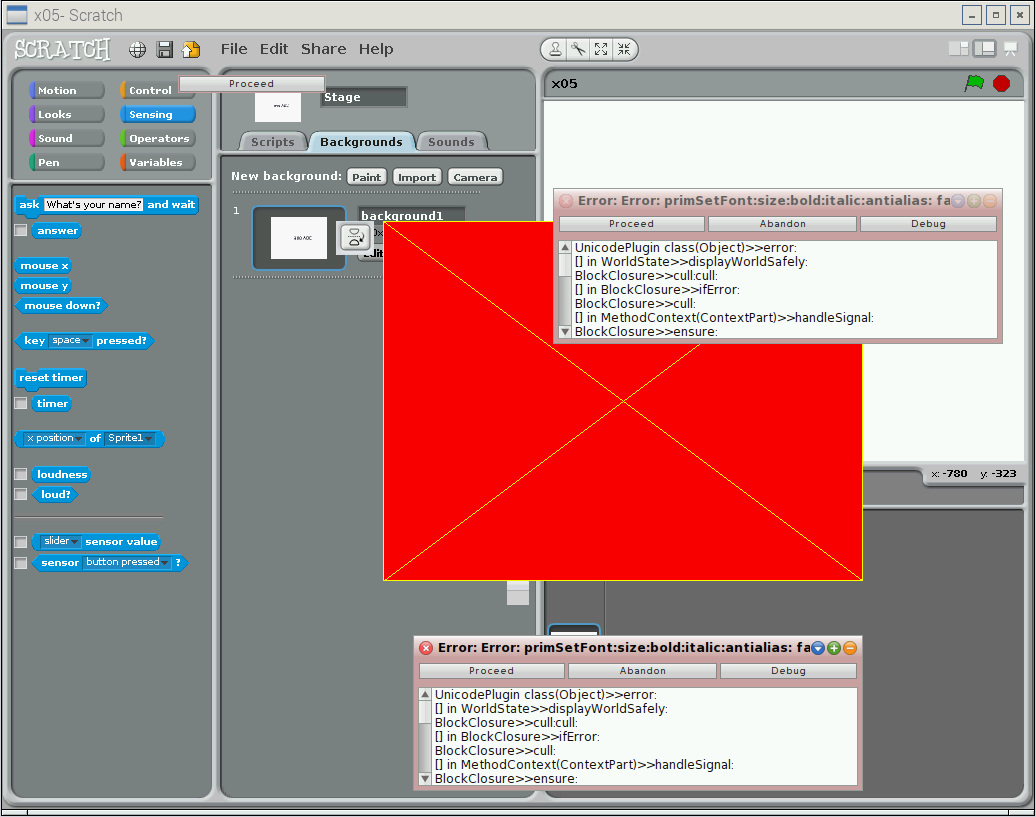
When work needs to be restored, click to the ‘proceed’-Button in the error messages. When one error message is away, there are quite a lot new of them might pop up. Always click ‘proceed’.

Then, look for background or sprites where fonts are used. You see it in the thumbnail preview in the costume tab.

‘edit’ these costumes. The editor has problems to start, and you get again many of these popups. pango_002

pango_003

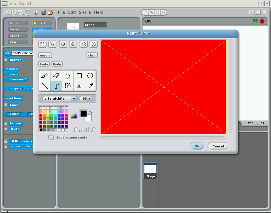
Editor window is displayed slowly, when it is back till you see the title bar of the editor “Paint Editor”, drag it around a little bit and the editor window will be redrawn to its usual appearance. Click to the ‘font’ button, this is the “T”-Button.

pango_004

You see  ‘a ScratchPan..’ in the font selector. Select a font from the selector. This clears the false value in this field. Commit the work with ‘ok’.

The sprite or background is restored. Now go ahead with the workaround procedure.

Workaround Procedure

Completed projects

If a project is completed, just avoid to save the project when leaving.

Projects during development

If the insertion of text is needed to costumes, then
– finalize the costume/background as usual.
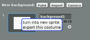
– export the costume to a file. Right click on the thumbnail image and ‘export this costume’.

pango_007

Then, use the import function and load this file into the costumes. The difference is that this is a bitmap copy, not containing the font. The problem is, that editing the text is no longer possible.
Delete the costume with the font.

 Comments

There is also an error report on raspberrypi-Forum. Leave a comment there.

RaspberrPi forum


scratchClient and piGlow

piGlow is a nice little board, providing 18 colored LED with an I2C-Controller.

With a major rework of the i2c-part of the scratchClient framework, I added support for this board / device in scratchClient.

Start it with

cd ~/scratchClient
sudo python src/scratchClient.py -c config/config_SN3218.xml 

The configuration uses some common variables to update the pwm-values in sync for all, for the ‘branches’ and – of course – the individual LED.
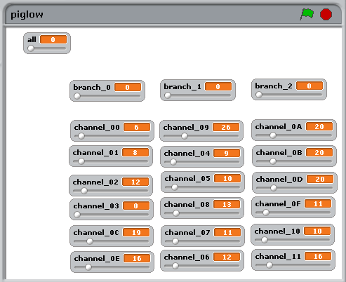
In the distribution, there is a simple scratch program, just providing variable definitions and some watchers on stage with sliders.
piglow_scratch

Not very graphic, I agree. But hopefully it saves some time in creating these 18 variable names (plus some more). It is in scratchClient/scratch/SN3218/piglow.sb

The branches are group names for the three wings arranged on the board.

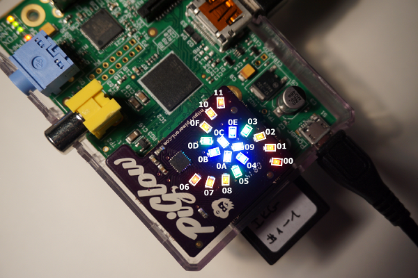
piglow_annotated

The above sketch shows the piglow board in action, annotated with the channel numbers in hex.

As indicated on the package of piGlow, the LED can be VERY bright when full power is applied. Looking into these light could harm your eyes.

But there is a trick to project an image of the LED to a remote screen (or the ceiling of my room).
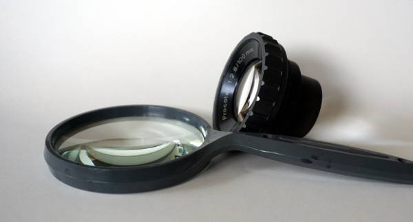
Use a magnifying glass or an objective lens.
lupe

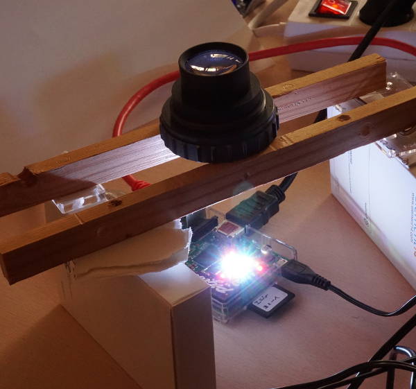
When adjusting the setup, be sure NOT to have the LED at full brightness.

aufbau

Place the lens in the correct distance in front of piGlow. I first tried out which distance is needed by hand, and then fine tuned the focus by adding sheets of paper. It was needed to place the lens in a stable position for the photograph.

result
The result on the ceiling, prox 0.3m large, 1.6m away. The dark grey structured background is the white ceiling, outshined by the image of the LED.

The center LED are opaque, the other LED show the bright chip inside the small package. The image in this setup was 15 times enlarged.
Again: never look into the bright light directly.